Audi Q3: Receiver/Dryer, Removing and Installing
 WARNING
Danger due to refrigerant coming out under pressure.
Danger of frost bite to skin and other parts of the body.
- Extract the refrigerant and immediately open the refrigerant circuit after that.
- If the refrigerant was extracted more than 10 minutes in the past and the refrigerant circuit was not opened, extract the refrigerant again. Pressure in the refrigerant circuit is caused by evaporation.
 Note
Note
- The receiver/dryer is only removed on the Showa/Keihin condenser.
- Depending on the version, the receiver/dryer is either completely replaced or only the dryer cartridge is replaced on the Showa/Keihin condenser (there are different versions. Refer to the Parts Catalog).
Special tools and workshop equipment required
- Engine Bung Set -VAS6122-
Removing
- Remove the lock carrier cover. Refer to → Body Exterior; Rep. Gr.63; Front Bumper; Attachments, Removing and Installing.
- Discharge the refrigerant circuit. Refer to → Refrigerant R134a, Servicing; Rep. Gr.87; Refrigerant Circuit (Refrigerant R134a, Servicing; Refrigerant Circuit, Using Service Station).
- Remove the front bumper cover. Refer to → Body Exterior; Rep. Gr.63; Front Bumper; Bumper Cover, Removing and Installing.
- For vehicles with a charge air cooler, remove the charge air cooler. Refer to → Rep. Gr.21; Charge Air System; Charge Air Cooler, Removing and Installing.
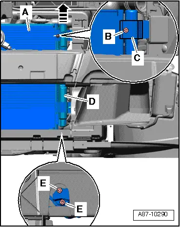
- Remove the bolts -E-.
- Remove the bolt -B- and then remove the bracket -C- downward.
- Remove the receiver/dryer -D- upward from the condenser -A--arrow-.
- Seal the open connections with clean plugs from the Engine Bung Set -VAS6122-.
Installing
Installation is done is reverse order, observe the following:
- Replace the O-ring seals. For the correct version, refer to the Parts Catalog.
 Note
Note
- Coat the O-ring seals lightly with refrigerant oil prior to installation. Refer to → Chapter "Refrigerant Circuit Seals".
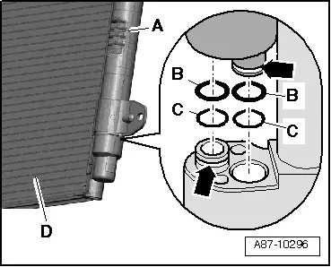
- Check the O-ring seals -B and C- for proper seating in the grooves -arrows- on the respective mount.
- Keep receiver/dryer closed as long as possible; do not remove caps until just before installing. receiver/dryer contains a desiccant bag which will become saturated with moisture in a short time if accumulator is left open. This makes the accumulator unusable.
- Clean the condenser contact surface -D- .
- Mount the receiver/dryer -A- on the condenser and tighten the bolts.
- For vehicles with a charge air cooler, install the charge air cooler. Refer to → Rep. Gr.21; Charge Air System; Charge Air Cooler, Removing and Installing.
- Install the front bumper cover. Refer to → Body Exterior; Rep. Gr.63; Front Bumper; Bumper Cover, Removing and Installing.
- Evacuate the refrigerant circuit and fill it. Refer to → Refrigerant R134a, Servicing; Rep. Gr.87; Refrigerant Circuit (Refrigerant R134a, Servicing; Refrigerant Circuit, Using Service Station).
- Operate the A/C system after filling the refrigerant circuit. Refer to → Chapter "A/C System, Starting Operation after Filling Refrigerant Circuit".
- Check the DTC memory and erase any displayed entries using the Vehicle Diagnostic Tester in the "Guided Fault Finding" function.
Tightening Specifications
- Receiver/dryer to condenser: 10 Nm
READ NEXT:
 Dryer Bag/Dryer Cartridge, Removing and Installing
Dryer Bag/Dryer Cartridge, Removing and Installing
WARNING
Danger due to refrigerant coming out under pressure.
Danger of frost bite to skin and other parts of the
body.
Extract the
Service Connection on Low and High Pressure Side, Removing and Installing
WARNING
Danger due to refrigerant coming out under pressure.
Danger of frost bite to skin and other parts of the
body.
Extract the refrigerant and immediately open the
refrigerant
SEE MORE:
Trim Molding, Removing and Installing
Special tools and workshop equipment
required
Wedge Set -T10383-
Removing
Note
Do not twist or bend the side window trim molding.
- Removing the roof trim molding. Refer to
→ Chapter "Roof Trim Molding, Removing and Installing".
- Tape off the area around the
Camera-based traffic sign recognition
Description
Applies to: vehicles with camera-based traffic sign recognition
Fig. 92 Instrument cluster: traffic sign recognition
The traffic sign recognition shows the traffic
signs detected by the front camera in the instrument
cluster display. Data from the navigation
system is also included in t
