Audi Q3: Component Location Overview - Components Outside of Passenger Compartment
Component Location Overview - Components Outside of Passenger Compartment, Front Component Group "1"
 Note
Note
Depending on the engine version to support the engine coolant pump an After-Run Coolant Pump -V51-/Heater Support Pump -V488- may be installed (different designations depending on the engine) (not shown in this illustration). Refer to → Engine Mechanical; Rep. Gr.19; Coolant System/Coolant (Connection Diagram for Coolant Hoses) and → Wiring diagrams, Troubleshooting & Component locations. The After-Run Coolant Pump -V51-/Heater Support Pump -V488- can be actuated in "stop mode" (engine stopped) to maintain the coolant flow rate through the heater core for the heater on with a cold engine or on vehicles with a Start/Stop System.
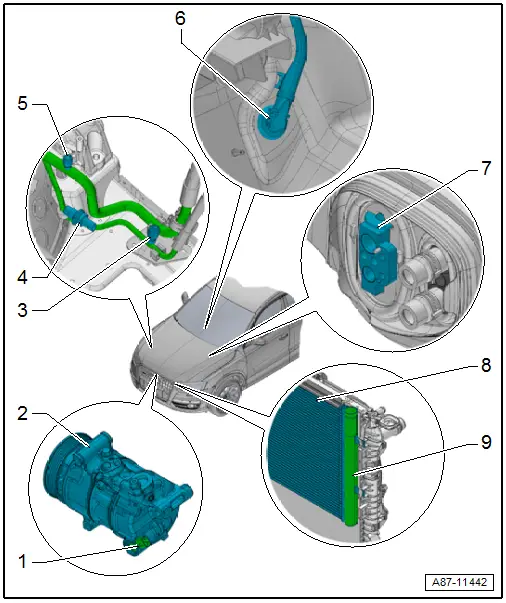
1 - A/C Compressor Regulator Valve -N280-
- Installed inside the A/C compressor
- To check, refer to Vehicle Diagnostic Tester in the "Guided Fault Finding" function, refer to → Chapter "A/C Compressor Regulator Valve -N280-, Checking Switch-On Signal" and → Wiring diagrams, Troubleshooting & Component locations.
 Note
Note
- Certain functions on the A/C Compressor Regulator Valve -N280- (for example, a stuck valve or a disruption in the coil) can lead to a complaint regarding the A/C compressor (A/C system doesn't cool, the evaporator ices over, etc.). If the cause is with the A/C Compressor Regulator Valve -N280- (and not the A/C compressor itself), the A/C compressor can be serviced by replacing the A/C Compressor Regulator Valve -N280-. Refer to → Refrigerant R134a Servicing; Rep. Gr.87; Refrigerant Circuit Components, Replacing (Refrigerant R134a, Servicing; Refrigerant Circuit Components, Replacing).
- The A/C Compressor Regulator Valve -N280- is not available as a replacement part for all A/C compressors. If the A/C Compressor Regulator Valve -N280- is not available as an individual A/C compressor part (different versions), then the entire A/C compressor must be replaced. Refer to the Parts Catalog.
2 - A/C Compressor
- There are different versions. Refer to the Parts Catalog.
- Overview. Refer to → Chapter "Overview - A/C Compressor Power Unit".
3 - High Pressure Side Service Connection
- for measuring, emptying and filling
 Caution
Danger due to refrigerant coming out under pressure when there is a defective valve in the refrigerant circuit.
Danger of frost bite to skin and other parts of the body.
Only remove when the refrigerant circuit is empty. The connection does not have a valve. Refer to → Refrigerant R134a Servicing; Rep. Gr.87; A/C System, General Information (Refrigerant R134a Servicing; A/C System, General Information).
- Overview. Refer to → Chapter "Overview - Condenser, A/C Compressor, Expansion Valve, Refrigerant Line".
4 - High Pressure Sensor -G65-
- To check, refer to Vehicle Diagnostic Tester in the "Guided Fault Finding" function, → Chapter "High Pressure Sensor -G65-, Checking Pressure Signal" and → Wiring diagrams, Troubleshooting & Component locations.
- Overview. Refer to → Chapter "Overview - Condenser, A/C Compressor, Expansion Valve, Refrigerant Line".
5 - Low Pressure Side Service Connection
- for measuring and emptying
 Caution
Danger due to refrigerant coming out under pressure when there is a defective valve in the refrigerant circuit.
Danger of frost bite to skin and other parts of the body.
Only remove when the refrigerant circuit is empty. The connection does not have a valve. Refer to → Refrigerant R134a Servicing; Rep. Gr.87; A/C System, General Information (Refrigerant R134a Servicing; A/C System, General Information).
- Overview. Refer to → Chapter "Overview - Condenser, A/C Compressor, Expansion Valve, Refrigerant Line".
6 - Condensation Water Drain
- Checking. Refer to → Chapter "Condensation Water Drain, Checking".
- Removing and installing. Refer to → Chapter "Condensation Water Drain, Removing and Installing".
7 - Expansion Valve
- Overview. Refer to → Chapter "Overview - Condenser, A/C Compressor, Expansion Valve, Refrigerant Line".
8 - Condenser
- Overview. Refer to → Chapter "Overview - Condenser, Dryer Cartridge".
9 - Receiver/Dryer
- Integrated in the condenser
- Overview. Refer to → Chapter "Overview - Condenser, Dryer Cartridge".
Component Location Overview - Components Outside of Passenger Compartment, Front Component Group "2"
 Note
Note
Depending on the engine version to support the engine coolant pump an After-Run Coolant Pump -V51-/Heater Support Pump -V488- may be installed (different designations depending on the engine) (not shown in this illustration). Refer to → Engine Mechanical; Rep. Gr.19; Coolant System/Coolant (Connection Diagram for Coolant Hoses) and → Wiring diagrams, Troubleshooting & Component locations. The After-Run Coolant Pump -V51-/Heater Support Pump -V488- can be actuated in "stop mode" (engine stopped) to maintain the coolant flow rate through the heater core for the heater on with a cold engine or on vehicles with a Start/Stop System.
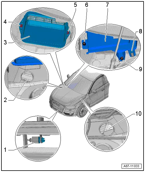
1 - Outside Air Temperature Sensor -G17-
- The measured value is evaluated by the Vehicle Electrical System Control Module -J519- and is transmitted to the Climatronic Control Module -J255-/A/C Control Module -J301- (the Heater Control Module -J65-) control head via the data bus.
- To check, refer to Vehicle Diagnostic Tester in the "Guided Fault Finding" function and → Wiring diagrams, Troubleshooting & Component locations.
- Removing and installing. Refer to → Chapter "Outside Air Temperature Sensor -G17-, Removing and Installing".
2 - Right Water Drain
- Checking. Refer to → Chapter "Plenum Chamber Water Drain, Checking".
3 - Fresh Air Intake
- Prevents foreign objects (such as leaves) from entering the A/C unit intake shroud
- Make sure it is seated properly
- Removing and installing. Refer to → Chapter "Fresh Air Intake, Removing and Installing".
4 - Nut
- 3 Nm
5 - Nut
- 3 Nm
6 - Bolt
- 3 Nm
7 - Fresh Air Intake Cover
- Removing and installing. Refer to → Chapter "Fresh Air Intake Cover, Removing and Installing".
8 - Air Quality Sensor -G238-
- Only with an automatic climate control system
- Function mode. Refer to → Chapter "Function of Air Quality Sensor -G238-".
- Checking. Refer to → Chapter "Air Quality Sensor -G238-, Checking".
- Removing and installing. Refer to → Chapter "Air Quality Sensor -G238-, Removing and Installing".
9 - Bolt
- 3 Nm
10 - Left Water Drain
- Checking. Refer to → Chapter "Plenum Chamber Water Drain, Checking".
Component Location Overview - Rear Components Outside of Passenger Compartment
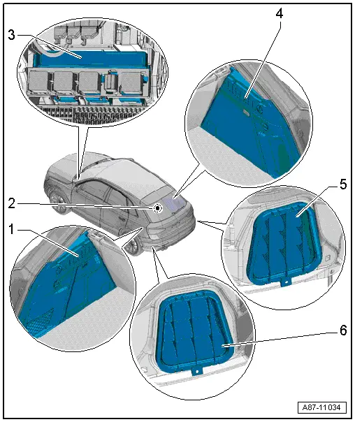
1 - Ventilation Slot in the Left Luggage Compartment
- There are different versions. Refer to the Parts Catalog.
- Checking. Refer to → Chapter "Passenger Compartment Forced Air Extraction, Checking".
2 - Rear Window Defogger -Z1-
- The request is sent by the Climatronic Control Module -J255-/A/C Control Module -J301- (the Heater Control Module -J65-) control head to the Vehicle Electrical System Control Module -J519- via the data bus. The activation occurs via the Vehicle Electrical System Control Module Vehicle Electrical System Control Module -J519-. Refer to Vehicle Diagnostic Tester in the "Guided Fault Finding" function and → Wiring diagrams, Troubleshooting & Component locations.
- Check:
- Manual climate control system (heater without A/C system). Refer to → Chapter "Rear Window Defogger -Z1-, Checking, Vehicles with Manual Climate Control System (Heater without A/C System)".
- Automatic climate control system. Refer to → Chapter "Rear Window Defogger -Z1-, Checking, Vehicles with Automatic Climate Control System".
- Rear window, removing and installing. Refer to → Body Exterior; Rep. Gr.64; Rear Window; Rear Window, Removing and Installing.
3 - Vehicle Electrical System Control Module -J519-
- The activation of various vehicle systems (for example, the Rear Window Defogger -Z1- etc.) as well as the evaluation of signals for other components occurs via the Vehicle Electrical System Control Module -J519-. Refer to Vehicle Diagnostic Tester in "Guided Fault Finding" function and → Wiring diagrams, Troubleshooting & Component locations.
- Removing and installing. Refer to → Electrical Equipment; Rep. Gr.97; Control Modules; Vehicle Electrical System Control ModuleJ519, Removing and Installing.
4 - Ventilation Slot in the Right Luggage Compartment
- There are different versions. Refer to the Parts Catalog.
- Checking. Refer to → Chapter "Passenger Compartment Forced Air Extraction, Checking".
5 - Right Forced Air Extraction
- There are different versions. Refer to the Parts Catalog.
- Checking. Refer to → Chapter "Passenger Compartment Forced Air Extraction, Checking".
- Removing and installing. Refer to → Chapter "Passenger Compartment Forced Air Extraction, Removing and Installing".
6 - Left Forced Air Extraction
- There are different versions. Refer to the Parts Catalog.
- Checking. Refer to → Chapter "Passenger Compartment Forced Air Extraction, Checking".
- Removing and installing. Refer to → Chapter "Passenger Compartment Forced Air Extraction, Removing and Installing".
READ NEXT:
 Component Location Overview - Components Inside Front Passenger
Compartment
Component Location Overview - Components Inside Front Passenger
Compartment
Component Location Overview - Components Inside Front Passenger
Compartment, Left Side of Passenger Compartment
1 - Left Footwell Vent
Overview. Refer to
→ Chapter "Overvie
System Overview - Refrigerant Circuit
HD = High-pressure end
ND = Low-pressure end
1 - A/C Compressor Regulator Valve -N280-
To check, refer to Vehicle Diagnostic Tester in the "Guided Fault
Finding" function,
→&nbSEE MORE:
Online radio
General information
Applies to: vehicles with Audi connect Infotainment and online
radio
You can listen to various radio stations or podcasts
on the Internet using online radio.
Requirement: the MMI must be connected to the
Internet. A data plan must be available.
Accessing online radio through the
Overview - Seat Pan Cover and Cushion
Overview - Seat Pan Cover and Cushion, Standard/Folding Seat
Note
The illustration shows versions with a fabric cover.
1 - Seat Pan
2 - Seat Cushion
Seat cover and cushion, removing and installing. Refer to
→ Chapter "Seat Pan Cover and Padding, Removin