Audi Q3: CV Joint, Servicing, Drive Axle with CV Joint, Inserted with Inner Splines
Special tools and workshop equipment required
- Seal Installer - Bevel Box -T10243-
- Torque Wrench 1331 5-50Nm -VAG1331-
- Clamping Pliers -VAG1682A-
- Press Piece - Multiple Use -VW447H-
- Copper or Brass Drift, commercially available
- Three arm extractor, for example the Puller - Kukko 3 Jaw - 100x100mm -12/1-
Removing Outer CV Joint
- Clamp the drive axle with protective jaws in a vise clamp.
- Open both clamping sleeves and remove protective joint boot from outer joint.
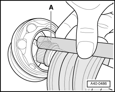
- Strike a copper or brass drift -A- on CV joint inner race with a hammer.
- Remove joint and protective joint boot.
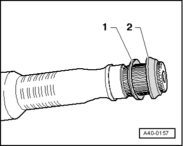
- If installed, remove the spring washer -1- and spacer ring -2-.

Installing the outer joint
- Joints and protective joint boots must be free of grease.
- Replace the circlip -1-.

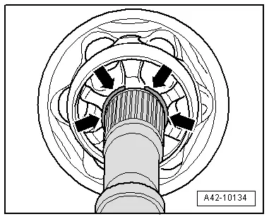
- If equipped, install the spring washer -1- and spacer ring -2- as shown in the illustration.
- Slide on the small clamp with the CV boot and position the CV boot on the drive axle.
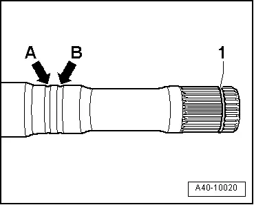
- Position the CV boot on the outer groove -arrow B-.
- Inner groove -arrow A- must remain visible "identification groove" (for correct installation of joint protective boot).
- Add approximately 70 % of the tube of grease to the inner joint.
- Before installing joint piece, splines -A- must be lightly coated with grease used in joint.
- Slide on CV joint up to sealing ring.
- Align sealing ring at center with opening upward -see arrows-.
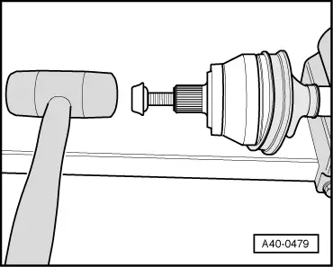
- Install the old drive axle screw into joint as shown in the illustration.
- Drive joint onto drive axle with plastic hammer until circlip engages.
- Add the rest of the grease into the joint on the boot side.
- Slide the protective boot onto the joint.
- Bleed protective joint boot.
- Make sure the protective boot is seated on the joint correctly.
- Protective joint boot must fit in groove and on joint contour.
- Tension the clamps on outer joint. Refer to → Fig. "Mount and Tension Stainless Steel Clamp using the Clamping Pliers -VAG1682A- as Illustrated".
Removing the Inner CV Joint
- Clamp the drive axle with protective jaws in a vise clamp.
- Fold back boot.
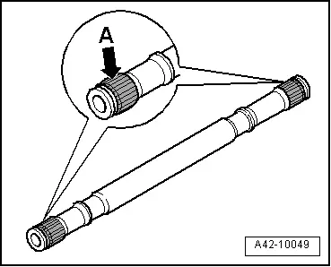
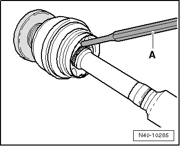
- Remove the CV joint from the drive axle using a drift -A-.
- Drift A must be installed exactly on the CV joint ball hub.
Installing the Inner CV Joint
- Drive onto shaft with plastic hammer until the circlip engages.
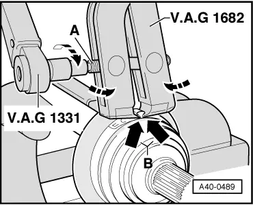
Mount and Tension Stainless Steel Clamp using the Clamping Pliers -VAG1682A- as Illustrated
- Attach the CV Joint Boot Clamp Tool -VAG1682- as illustrated. When doing this, make sure that edges of clamping pliers are seated in corners -arrows B- of clamp.
- Tension clamp by turning spindle with a torque wrench (do not tilt clamp tool).
 Note
Note
- A stainless steel clamp must be used due to hardness of CV boot material (compared to rubber). This clamp can only be tensioned using Clamping Pliers -VAG1682A-.
- Tightening specification: 25 Nm.
- Use torque wrench -C- with adjustment range 5...50 Nm (for example Torque Wrench 1331 5-50Nm -VAG1331-).
- Make sure the threads on the spindle -A- on the pliers move easily. Lubricate with MOS 2 grease, if necessary.
- If the thread is tight, for example, dirty, the required tensioning force for the hose clamp will not be achieved in spite of correct torque specification settings.
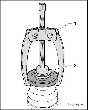
Removing the Cap from the CV Joint
1 - Three arm extractor, for example Kukko 45-2
2 - Press Piece - Multiple Use -VW447H-
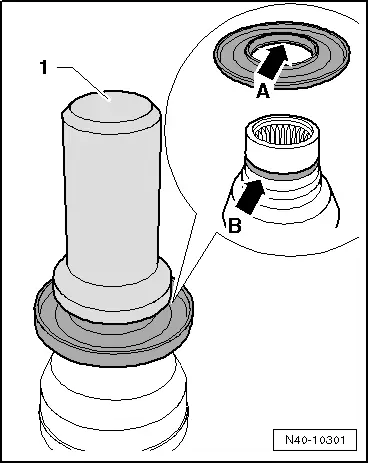
Mounting the Cap onto the CV Joint
1 - Seal Installer - Bevel Box -T10243-
Mount the cap far enough onto the joint until the ridge -arrow A- fits into the groove -arrow B-.
READ NEXT:
 Outer CV Joint, Checking
It is necessary to disassemble the joint whenever replacing
the grease or if the ball surfaces show wear or damage.
Removing
- Before disassembling mark ball hub position in relation to
the
Special Tools
Special tools and workshop equipment required
Bearing Installer - Wheel Hub/Bearing Kit -T10205-
Torque Wrench 1332 40-200Nm -VAG1332-
Hydraulic Press -VAS6178-
Pneumatic/Hydraulic Foot Pu
SEE MORE:
Starting and stopping the engine automatically
Applies to: vehicles with Start/Stop system
The system checks if certain conditions are met
before and during the Stop phase, and determines
if the engine stops and how long it remains
stopped. For example, if power usage is
high, the engine will not be stopped. Along with
other conditions, the foll
General information
Selecting the radio
Fig. 136 Center display: FM station list
Fig. 137 Center display: SiriusXM station list
Depending on the vehicle equipment, the radio
may support the FM, AM, and SiriusXM (satellite
radio) frequency bands. Using the HD Radio receiver
also allows you to receive radio stations
on
