Audi Q3: Electronic Damping
Overview - Electronic Damping Component Location
 Note
Note
The body acceleration sensors may not be interchanged with each other.
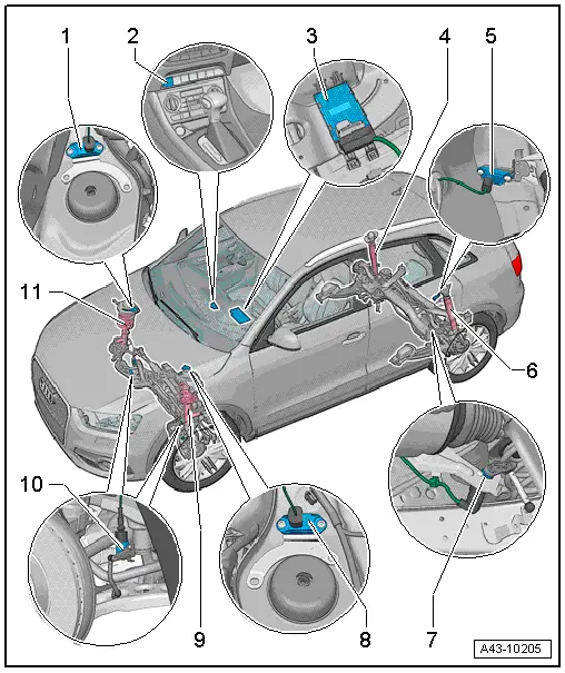
1 - Right Front Body Acceleration Sensor -G342-
- Removing and installing. Refer to → Chapter "Left/Right Front Body Acceleration Sensor -G341-/-G342-, Removing and Installing".
2 - Driving Profile Selection Switch Module -E592-
- Component location: the Driving Profile Selection Switch Module -E592- is installed in the center console selector unit.
3 - Electronic Damping Control Module -J250-
- Removing and installing. Refer to → Chapter "Electronic Damping Control Module -J250-, Removing and Installing".
- Component location: the Electronic Damping Control Module -J250- is installed under the right front seat.
- If the Electronic Damping Control Module -J250- was replaced, a basic setting for the electronic damping must be performed. Refer to Vehicle Diagnosis Tester.
4 - Shock Absorber with Right Rear Damping Adjustment Valve -N339-
- Shock absorber, removing and installing. Refer to → Chapter "Shock Absorber, Removing and Installing".
- Shock absorber, servicing. Refer to → Chapter "Shock Absorber, Servicing".
5 - Rear Body Acceleration Sensor -G343-
- Removing and installing. Refer to → Chapter "Rear Body Acceleration Sensor -G343-, Removing and Installing".
6 - Shock Absorber with Left Rear Damping Adjustment Valve -N338-
- Shock absorber, removing and installing. Refer to → Chapter "Shock Absorber, Removing and Installing".
- Shock absorber, servicing. Refer to → Chapter "Shock Absorber, Servicing".
7 - Left Rear Level Control System Sensor -G76-
- Removing and installing. Refer to → Chapter "Left/Right Rear Level Control System Sensor -G76-/-G77-, Removing and Installing".
8 - Left Front Body Acceleration Sensor -G341-
- Removing and installing. Refer to → Chapter "Left/Right Front Body Acceleration Sensor -G341-/-G342-, Removing and Installing".
9 - Shock Absorber with Left Front Damping Adjustment Valve -N336-
- Suspension strut, removing and installing. Refer to → Chapter "Suspension Strut, Removing and Installing".
- To service the suspension strut. Refer to → Chapter "Suspension Strut, Servicing".
10 - Left Front Level Control System Sensor -G78-
- Removing and installing. Refer to → Chapter "Left/Right Front Level Control System Sensor -G78-/-G289-, Removing and Installing".
11 - Shock Absorber with Right Front Damping Adjustment Valve -N337-
- Suspension strut, removing and installing. .
- To service the suspension strut.
Electronic Damping Control Module -J250-, Removing and Installing
Special tools and workshop equipment required
- Vehicle Diagnostic Tester
- Carpet Knife, commercially available
Removing
The Electronic Damping Control Module -J250- is installed under the right front seat.
- Detach the right front seat and tilt it to back. Refer to → Body Interior; Rep. Gr.72; Front Seats; Front Seat, Removing and Installing, while being careful not to damage any components.
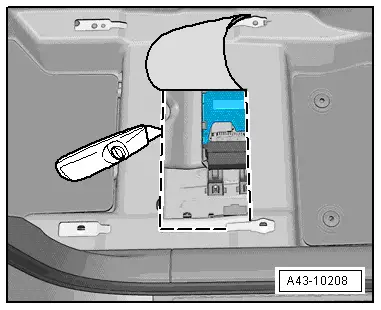
- Cut carpet at markings as shown using a standard carpet knife.
- Fold up the carpet.
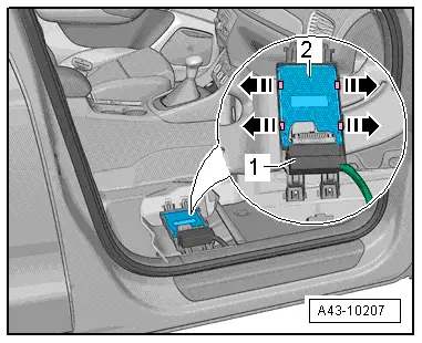
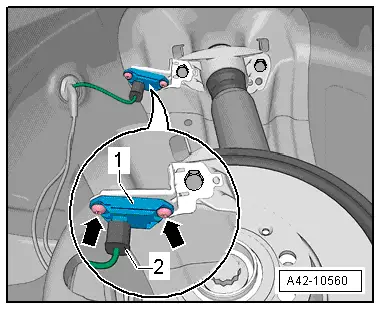
- Unclip the Electronic Damping Control Module -J250--2- from the bracket -arrows- and remove it from the E-box.
- Disconnect the connector -1-.
Installing
Installation is reverse of removal, noting the following:
- Install the front seat. Refer to → Body Interior; Rep. Gr.72; Front Seats; Front Seat, Removing and Installing, while being careful not to damage any components.
- If the Electronic Damping Control Module -J250- was replaced, a basic setting for the electronic damping must be performed. Refer to Vehicle Diagnosis Tester.
Left/Right Front Body Acceleration Sensor -G341-/-G342-, Removing and Installing
Left/Right Front Body Acceleration Sensor -G341-/-G342-, Removing and Installing
Special tools and workshop equipment required
- Torque Wrench 1410 -VAG1410-
Removing
- Remove the plenum chamber cover. Refer to → Body Exterior; Rep. Gr.50; Bulkhead; Plenum Chamber Cover, Removing and Installing.
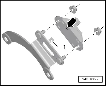
- Release and disconnect the connector -arrow-.
- Remove the bolts -2- and remove the front body acceleration sensor -1- from the bracket.
Installing
Install in reverse order of removal. Note the following:
 Caution
The Front Body Acceleration Sensors -G341-/-G342- must never be interchanged with the rear body acceleration sensor. For allocation. Refer to the Parts Catalog.
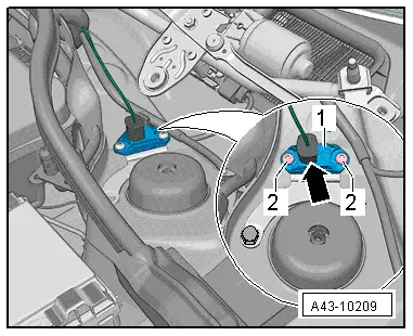
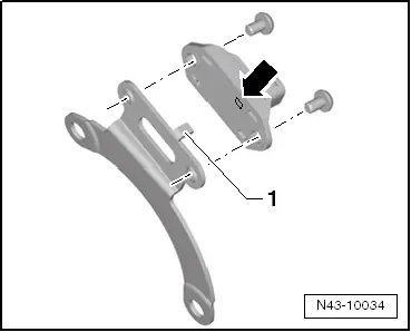
Installation position of Front Body Acceleration Sensor on Bracket, Observing
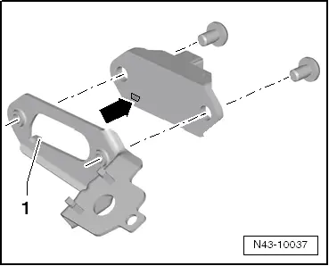
- The tab on the bracket -1- must engage in the recess on the front body acceleration sensor -arrow-.
 Note
Note
Be sure to use the correct retainer. An "L" or "R" is stamped on the bracket.
- Install the plenum chamber cover. Refer to → Body Exterior; Rep. Gr.50; Bulkhead; Plenum Chamber Cover, Removing and Installing.
Front Body Acceleration Sensor Bracket, Removing and Installing
Special tools and workshop equipment required
- Torque Wrench 1331 5-50Nm -VAG1331-
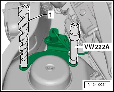
- Pilot Drift -VW222A-
- Spiral bore diameter: 11 mm
Removing
- Remove the front body acceleration sensor. Refer to → Chapter "Left/Right Front Body Acceleration Sensor -G341-/-G342-, Removing and Installing".
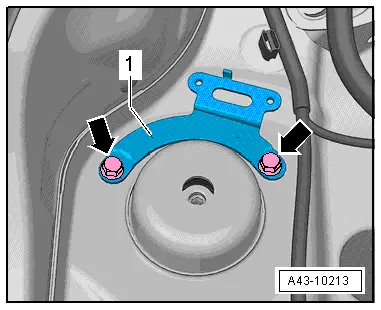
- Remove the bolts -arrows- and remove the bracket -1- from the shock absorber dome.
Installing
 Caution
The body acceleration sensors must not be interchanged. For the allocation. Refer to the Parts Catalog.
- Clean the shock absorber dome.
Left Front Body Acceleration Sensor -G341-
- Attach the Left Front Body Acceleration Sensor -G341- to the bracket.
- Note the installation position of the Left Front Body Acceleration Sensor -G341- on the bracket.
- The tab on the bracket -1- must engage in the recess on the Left Front Body Acceleration Sensor -G341--arrow-.
 Note
Note
Be sure to use the correct retainer. An "LA" is stamped on the retainer

Right Front Body Acceleration Sensor -G342-
- Attach the Right Front Body Acceleration Sensor -G342- to the bracket.
- Note the installation position of the Right Front Body Acceleration Sensor -G342- on the bracket.
- The tab on the bracket -1- must engage in the recess on the Right Front Body Acceleration Sensor -G342--arrow-.
 Note
Note
Be sure to use the correct retainer. An "R" is stamped on the retainer.
Continued for both sides
- Remove the adhesive seal on the bracket or attach double-sided adhesive tape.
- Using an 11 mm drill, secure the bracket and the Pilot Drift -VW222A-.
 Note
Note
The holes in the bracket must align with the holes in the shock absorber dome.
- Install the bolts one after the other hand-tight and then tighten to the tightening specification.
- Connect the connector to the body acceleration sensor.
Rear Body Acceleration Sensor -G343-, Removing and Installing
Special tools and workshop equipment required
- Torque Wrench 1410 -VAG1410-
Removing
- Remove the left rear wheel. Refer to → Chapter "Wheels and Tires".
- Remove the left rear wheel housing liner. Refer to → Body Exterior; Rep. Gr.66; Wheel Housing Liner; Rear Wheel Housing Liner, Removing and Installing.
- Disconnect the connector -2-.
- Remove the bolts -arrows- and remove the Rear Body Acceleration Sensor -G343--1-.
Installing
Install in reverse order of removal. Note the following:
 Caution
The rear body acceleration sensor must not be interchanged with the front body acceleration sensors. For allocation. Refer to the Parts Catalog.
- Note the Rear Body Acceleration Sensor -G343- installation position on the bracket.
- The tab on the bracket -1- must engage in the recess on the Rear Body Acceleration Sensor -G343--arrow-.
- Install the left rear wheel housing liner. Refer to → Body Exterior; Rep. Gr.66; Wheel Housing Liner; Rear Wheel Housing Liner, Removing and Installing.
- Install the left rear wheel. Refer to → Chapter "Wheels and Tires".
READ NEXT:
 Level Control System Sensor
Overview - Front Level Control System Sensor
Note
A replacement Left Front Level Control System Sensor -G78- and Right
Front Level Control Sensor -G289- only comes complete with the coupl
Vehicle Alignment
Axle Alignment Information
Wheel alignment must only performed using VW/Audi-approved
wheel alignment equipment.
Each time wheels are aligned, both front and rear wheels
must be aligned.
Otherw
SEE MORE:
Finish Balancer
Caution
For the balancing, the wheels of the tractive axle
are set upon the turntable sensors, for example, front
wheels for Front Wheel Drive (FWD) and all 4 wheels for
All Wheel Drive (AWD).
Note
Working with a finish balancer requires instruction from the
manufacture
Acceptable Tread Depth Variance
Model with Longitudinally Installed Engine
Tread variance for models with a longitudinally installed
engine, such as A4, A5, A6, A7, A8, Q5, Q7, ...
The variance between the front and rear axle in this case
may not be more then 2 mm
Note
The technical background of the limitations a
