Audi Q3: Level Control System Sensor
Overview - Front Level Control System Sensor
 Note
Note
A replacement Left Front Level Control System Sensor -G78- and Right Front Level Control Sensor -G289- only comes complete with the coupling rod and the upper and lower retaining plate.
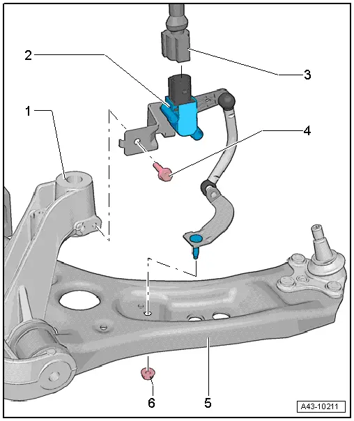
1 - Subframe
2 - Left Front Level Control System Sensor -G78- and Right Front Level Control Sensor -G289-
- Complete with components
- The lever must face toward outside of vehicle
- If the Left Front Level Control System Sensor -G78- or the Right Front Level Control Sensor -G289- is being removed and installed, then a basic setting for the electronic damping must be performed. Refer to Vehicle Diagnosis Tester.
- Removing and installing. Refer to → Chapter "Left/Right Front Level Control System Sensor -G78-/-G289-, Removing and Installing".
3 - Connector
4 - Bolt
- 9 Nm
5 - Control Arm
6 - Nut
- 9 Nm
- Always replace if removed
Overview - Rear Level Control System Sensor
 Note
Note
The Left Rear Level Control System Sensor -G76- and Right Rear Level Control System Sensor -G77- is only available as a replacement part together with the connecting link and upper and lower mounting plates.
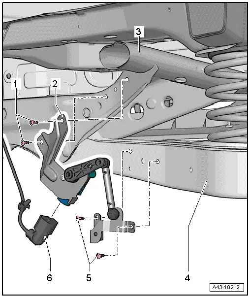
1 - Bolt
- 5 Nm
2 - Left Rear Level Control System Sensor -G76- and Right Rear Level Control System Sensor -G77-
- Complete with components
- The lever must face toward outside of vehicle
- Removing and installing. Refer to → Chapter "Left/Right Rear Level Control System Sensor -G76-/-G77-, Removing and Installing".
- If the Left Rear Level Control System Sensor -G76- and Right Rear Level Control System Sensor -G77- was removed and installed, then the basic setting for the electronic damping must be performed using the Vehicle Diagnosis Tester
- Perform a basic setting on the headlamps after replacing them Vehicle Diagnosis Tester
3 - Subframe
4 - Lower Control Arm
5 - Bolt
- 5 Nm
6 - Connector
Left/Right Front Level Control System Sensor -G78-/-G289-, Removing and Installing
Special tools and workshop equipment required
- Torque Wrench 1331 5-50Nm -VAG1331-
Removing
 Note
Note
- In order to be able to remove the Left Front Level Control System Sensor -G78- the steering wheel must be turned all the way to the left; this assures that there is enough clearance between the control arm and the stabilizer bar.
- In order to be able to remove the Right Front Level Control Sensor -G289- the steering wheel must be turned all the way to the right; this assures that there is enough clearance between the control arm and the stabilizer bar.
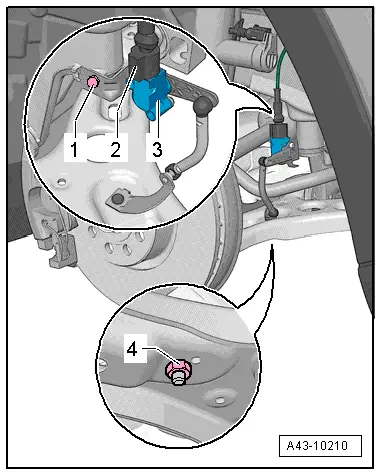
- Disconnect the connector -2-.
- Remove the nut -4- and bolt -1-.
- Remove the level control system sensor -3-.
Installing
Install in reverse order of removal. Note the following:
 Note
Note
- The level control system sensor lever must point toward vehicle exterior.
- The thread on the vehicle level sensor must be installed into the front hole in the control arm. The tab on the vehicle level sensor retainer must lock into the rear hole in order to assure a correct installation position.
- On vehicles with electronically controlled damping, perform the function "Adapt the control position" with the Vehicle Diagnosis Tester.
- If the control position was reprogrammed and if the vehicle has lane assist, then it will then be necessary to calibrate the driver assistance systems front camera. Refer to → Chapter "Driver Assistance Systems Front Camera, Calibrating".
- On vehicles with level control system sensor, perform headlamp basic setting. Refer to → Electrical Equipment; Rep. Gr.94; Headlamp, Adjusting.
Left/Right Rear Level Control System Sensor -G76-/-G77-, Removing and Installing
Special tools and workshop equipment required
- Torque Wrench 1331 5-50Nm -VAG1331-
Removing
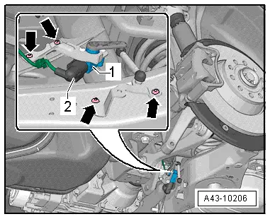
- Disconnect the connector -2-.
- Remove the bolts -arrows-.
- Remove the Right Rear Level Control System Sensor -G77- or Left Rear Level Control System Sensor -G76--1-.
Installing
Install in reverse order of removal. Note the following:
The level control system sensor lever must point toward vehicle exterior.
- On vehicles with electronically controlled damping, perform the function "Adapt the control position" with the Vehicle Diagnosis Tester.
- If the control position was reprogrammed and if the vehicle has lane assist, then it will then be necessary to calibrate the driver assistance systems front camera. Refer to → Chapter "Driver Assistance Systems Front Camera, Calibrating".
- On vehicles with level control system sensor, perform headlamp basic setting. Refer to → Electrical Equipment; Rep. Gr.94; Headlamp, Adjusting.
Special Tools
Special tools and workshop equipment required
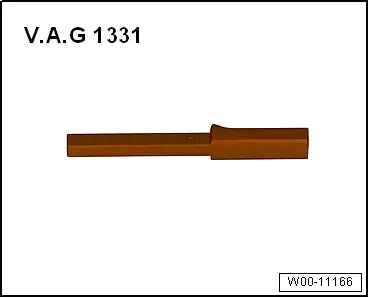
- Torque Wrench 1331 5-50Nm -VAG1331-
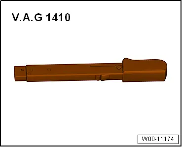
- Torque Wrench -VAG1410-
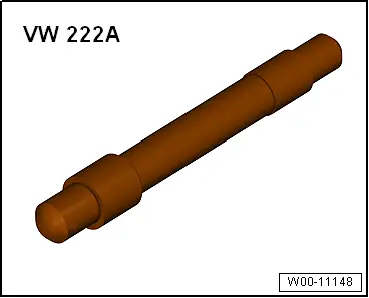
- Pilot Drift -VW222A-
