Audi Q3: General Information
ABS Repair Instructions
ABS malfunctions do not affect the brake system and the booster. Conventional brake system stays operative even without ABS. A change in braking behavior should be checked. When the ABS warning lamp comes on the rear wheels can lock-up early when braking!
 WARNING
- The ABS is generally maintenance-free.
- Testing, assembly, and repair work may only be performed by qualified personnel.
- By not observing the points described in the repair manual, the system can be damaged and vehicle safety could be compromised.
The brake system is distributed diagonally. The vacuum brake servo unit boosts the brakes pneumatically.
Malfunction sources are reduced by direct connection of components named. The components are replaced instead of repaired.
- Before performing repair work on the anti-lock brake system, determine the cause of the malfunction using On-Board Diagnostics (OBD).
- When installing a new hydraulic control unit, the coding must be checked, refer to Vehicle Diagnostic Tester.
- Turn off the ignition and disconnect the battery Ground (GND) cable.
- When working with brake fluid, observe relevant safety precautions and notes, refer to → Chapter "Brake Fluid General Information".
- Bleed the brake system with the Brake Charger/Bleeder Unit -VAS5234- for all work that requires opening the hydraulic system. High and low pressure testing should also be performed on the brake system, refer to → Chapter "Checking for Leaks".
- During the final road test, ensure that a ABS-controlled brake test is performed at least once (pulsation must be felt at the brake pedal), refer to Vehicle Diagnostic Tester.
Component Location Overview
Component Location Overview - ABS/ESP
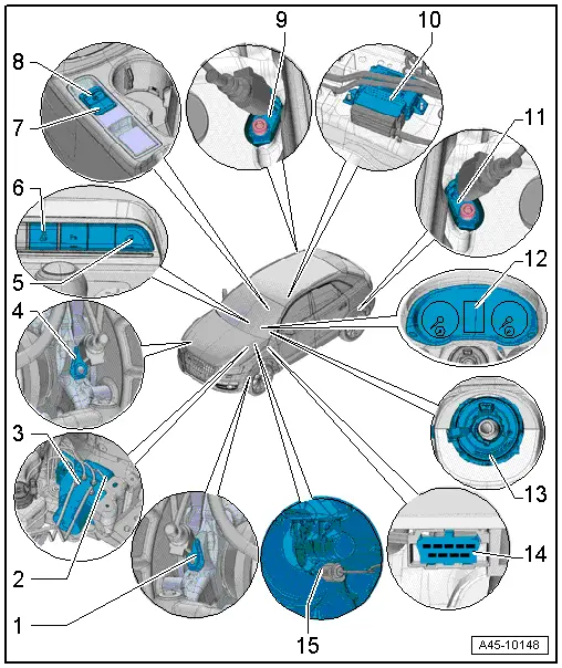
1 - Left Front ABS Wheel Speed Sensor -G47-
- Can be checked in the "Guided Fault Finding", refer to Vehicle Diagnostic Tester
- Removing and installing, refer to → Chapter "Right/Left Front ABS Wheel Speed Sensor -G45-/-G47-, Removing and Installing".
2 - ABS Hydraulic Unit -N55-
- Component location: under the battery in the engine compartment on the left
- The hydraulic unit consists of the components:
- Brake Pressure Sensor 1 -G201- cannot be replaced.
- ABS Hydraulic Pump -V64- cannot be replaced.
- Valve block (containing the intake and exhaust valves) cannot be replaced.
- The ABS Hydraulic Pump -V64- and valve block must not be separated from one another.
- ABS Hydraulic Unit -N55- must not be separated from the ABS Control Module -J104-
- Overview, refer to → Chapter "Overview - Control Module and Hydraulic Unit".
3 - ABS Control Module -J104-
- Component location: on the hydraulic unit under the battery in the engine compartment to the left
- Do not disconnect connector before successfully completing On Board Diagnostic (OBD). Switch ignition off before separating connector
- ABS Control Module -J104- must not be separated from the ABS Hydraulic Unit -N55-
- Removing and installing, refer to → Chapter "ABS Control Module -J104-/ABS Hydraulic Unit -N55-, Removing and Installing".
4 - Right Front ABS Wheel Speed Sensor -G45-
- Removing and installing, refer to → Chapter "Right/Left Front ABS Wheel Speed Sensor -G45-/-G47-, Removing and Installing".
5 - ASR/ESP Button -E256-
- Can be checked in the "Guided Fault Finding" refer to Vehicle Diagnostic Tester
- Installed location: In the center console
6 - Hill Descent Control Button -E618-
- Installed location: In the center console
7 - Electromechanical Parking Brake Button -E538-
- Removing and installing, refer to → Electrical Equipment; Rep. Gr.96; Controls; Electromechanical Parking Brake Button E538/ -AUTO HOLD- Button E540, Removing and Installing.
8 - -AUTO HOLD- Button -E540-
- Removing and installing, refer to → Electrical Equipment; Rep. Gr.96; Controls; Electromechanical Parking Brake Button E538/ -AUTO HOLD- Button E540, Removing and Installing.
9 - Right Rear ABS Wheel Speed Sensor -G44-
- Can be checked in the "Guided Fault Finding", refer to Vehicle Diagnostic Tester
- Removing and installing, refer to → Chapter "Right/Left Rear ABS Wheel Speed Sensor -G44-/-G46-, Removing and Installing".
10 - Electromechanical Parking Brake Control Module -J540-
- Component location: under the center console
- Installed together with Transverse Acceleration Sensor -G200-, Rotation Rate Sensor -G202- and Longitudinal Acceleration Sensor -G251- in one housing
- Removing and installing, refer to → Chapter "Electromechanical Parking Brake Control Module -J540-, Removing and Installing".
11 - Left Rear ABS Wheel Speed Sensor -G46-
- Can be checked in the "Guided Fault Finding", refer to Vehicle Diagnostic Tester
- Removing and installing, refer to → Chapter "Right/Left Rear ABS Wheel Speed Sensor -G44-/-G46-, Removing and Installing".
12 - Instrument Cluster
- With
- ABS Indicator Lamp -K47-
- Brake System Indicator Lamp -K118-
- ASR/ESP Indicator Lamp -K155-
- Electromechanical Parking Brake Indicator Lamp -K213-
- For removing and installing, refer to → Electrical Equipment; Rep. Gr.90; Instrument cluster.
13 - Steering Column Electronics Control Module -J527-
- With Airbag Spiral Spring/Return Spring with Slip Ring -F138- and Steering Angle Sensor -G85-
- Removing and installing, refer to → Electrical Equipment; Rep. Gr.94; Steering Column Switch Module; Steering Column Electronics Control ModuleJ527, Removing and Installing.
14 - Brake Lamp Switch -F-
- Installed location: on the master brake cylinder
- Removing and installing, refer to → Chapter "Brake Lamp Switch, Removing and Installing".
15 - Data Link Connector (DLC)
- Component location: in the instrument panel cover on the driver side
READ NEXT:
 Control Module and Hydraulic Unit
Overview - Control Module and Hydraulic Unit
1 - Brake Booster
Removing and installing, refer to
→ Chapter "Brake Booster, Removing and Installing".
2 - Brake Li
Sensors
Overview - Front Axle Speed Sensor
1 - Wheel Speed Sensor
Right Front ABS Wheel Speed Sensor -G45-/Left Front ABS Wheel Speed
Sensor -G47-
Removing and installing, refer to
→&
SEE MORE:
Tire pressure monitoring system
General notes
Each tire, including the spare (if provided),
should be checked monthly when cold and inflated
to the inflation pressure recommended by the
vehicle manufacturer on the vehicle placard or
tire inflation pressure label. (If your vehicle has
tires of a different size than the size indica
New tires or wheels
Audi recommends having all work
on tires or wheels performed by
an authorized Audi dealer or authorized
Audi Service Facility.
These facilities have the proper
knowledge and are equipped with
the required tools and replacement
parts.
New tires do not yet have the
optimal gripping properties.
Dr
