Audi Q3: General, Technical data
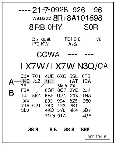
Identification
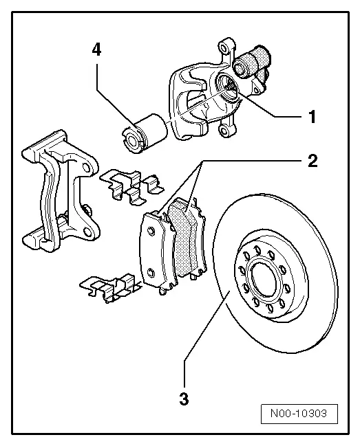
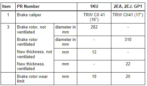
Brake PR Numbers
The PR number on the vehicle data label describes which brake system is installed in the vehicle.
Example of a Vehicle Data Sticker:
A - Front Brakes (example)
B - Rear Brakes (example)
- Allocation, refer to the Parts Catalog.
- The tables (Refer to → Chapter "Brakes Technical Data".) explain the PR numbers. These are important for the combination brake caliper/brake disc and brake pad.
Safety Precautions
Start/Stop System Safety Precautions
Pay attention to the following when working on a vehicle with Stop/Start system:
 WARNING
There is a risk of injury if the engine starts automatically in vehicles with the Start/Stop System.
- For vehicles with an activated Start/Stop System (recognizable from a notification in the instrument cluster), the motor can be started automatically if needed.
- Make sure the Start/Stop System is disabled when working on the vehicle (turn off ignition, if needed, turn the ignition back on).
Road Test with Testing Equipment Safety Precautions
If testing equipment must be used during a road test, observe the following:
 WARNING
Distraction and testing equipment that is not secured properly can cause accidents.
The passenger airbag could pose a risk if it deploys in a collision.
- Operating testing equipment while driving causes it to shift position.
- There is an increased risk of injury due to unsecured testing equipment.
Always secure testing equipment on the rear seat with a strap. Have a second technician in the back to operate the equipment.
Repair Information
Clean Working Conditions
- Absolute cleanliness is required when working on the ABS, it is not permitted to use any products which contain mineral oil, such as oils, greases etc.
- Thoroughly clean all unions and the adjacent areas before loosening. Do not use aggressive cleaning agents such as brake cleaner, fuel, thinners or similar chemicals.
- Place parts that have been removed on a clean surface and cover.
- Carefully cover over opened components or seal, if repairs are not performed immediately (use sealing plugs from Repair Kit -1H0 698 311 A-).
- Only use lint-free cloths.
- Only unpack replacement parts immediately prior to installation.
- Only use parts in their original packaging.
- If system is open, do not work with compressed air and do not move the vehicle.
- Make sure that brake fluid does not enter harness connectors.
General Repair Information
- Hairline cracks on brake rotor friction surfaces are often observed during brake repairs. Hairline cracks up to 10 mm long are not a technical flaw and are not cause for brake rotor replacement.
- Brake discs with brake pads that have worn through should be replaced.
Contact Corrosion
Contact corrosion can occur if incorrect fasteners (bolts, nuts, washers, etc.) are used.
For this reason, only fastening elements with a special surface coating are installed.
Also, rubber or plastic parts and adhesive consist of non-conductive materials.
If there are doubts about whether parts can be used or not, then use new parts, refer to the Parts Catalog.
 Note
Note
- Only original replacement parts are recommended, they are checked and compatible with aluminum.
- It is recommended to use Audi accessories.
- Damage resulting from contact corrosion is not covered by the warranty.
Technical Data
Brakes Technical Data
Front Brakes Technical Data
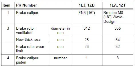
- Allocation, refer to the Parts Catalog.
- Wear limits for the brake pads.
Rear Brakes Technical Data
- Allocation, refer to the Parts Catalog.
- Wear limits for the brake pads.
Brakes Inspection
General Information
- The testing takes place on a test stand.
- When testing, manual transmission vehicles must be in idle and automatic transmission vehicles must be in driving position N.
- Always observe the test stand manufacturer instructions.
 Note
Note
Electronic brake control systems are inoperative when the ignition is switched off.
Front Wheel Drive Vehicles, Checking
- The brake test is to be performed on a one-axle roller test stand.
- The test speed must not exceed 5 km/h (3 mph), otherwise, the brakes may lock up due to the roller start-up delay (EDL regulation).
- Test stands approved by Audi meet these requirements.
All Wheel Drive Vehicles, Checking
Testing on a One-Axle Roller Test Stand for AWD Vehicles
- During this test, the wheels of one axle are driven in opposite directions, to prevent delivering power to the other axle.
- The test speed must not exceed 6 km/h (4 mph), otherwise, the brakes may lock up due to the roller start-up delay (EDL regulation).
- Test stands approved by Audi meet these requirements.
Parking Brake, Checking
Test Sequence
- Drive in vehicle with rear wheels onto test rollers and do not switch off ignition.
 Note
Note
Do not switch off the ignition.
- As soon as the rollers reach a speed above 3 km/h (2 mph). the "TÜV mode" is activated.
- The yellow electro-mechanical parking brake symbol with a line through it appears in the instrument cluster, refer to the Owner's Manual, Instruments and Indicator Lamps
The Electro-Mechanical Parking Brake Function Is Now:
- The brakes do not close at once, but rather close a bit each time the Electromechanical Parking Brake Button -E538- is pressed. The brake is completely closed in three stages.
- Pressing the Electromechanical Parking Brake Button -E538- releases the brakes again.
Prerequisite for "TÜV mode":
- Ignition on
- Front wheels, speed = 0 km/ h
- Rear wheels, speed min. = 3, max. 9 km/h.
 WARNING
A brake test stand with a regulated wheel set must be used on AWD vehicles.
READ NEXT:
 General Information
ABS Repair Instructions
ABS malfunctions do not affect the brake system and the
booster. Conventional brake system stays operative even without
ABS. A change in braking behavior should be checked
Control Module and Hydraulic Unit
Overview - Control Module and Hydraulic Unit
1 - Brake Booster
Removing and installing, refer to
→ Chapter "Brake Booster, Removing and Installing".
2 - Brake Li
SEE MORE:
Side Air Intake Trim, Removing and Installing, Audi RS Q3 through MY 2014
Removing
- Left: remove the front bumper cover. Refer to
→ Chapter "Bumper Cover, Removing and Installing".
- Right: remove the front wheel housing liner and wheel
spoiler. Refer to
→ Chapter "Front Wheel Housing Liner, Removing and Installing".
- Carefully remov
Automatic luggage compartment lid
Applies to: vehicles with automatic luggage compartment
Fig. 30 Luggage compartment lid: 1 closing button, 2
lock button (vehicles with convenience key)
The luggage compartment lid can be opened and
closed automatically.
Opening the luggage compartment lid
When the ignition is switched off, press
