Audi Q3: Stabilizer Bar
Overview - Stabilizer Bar
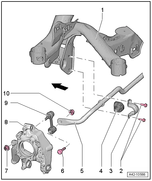
1 - Subframe
2 - Bolt
- 25 Nm + 45º
- Always replace if removed
- Install evenly
3 - Clamp
4 - Bearing
- Always replace the rubber mounts on both sides of vehicle
5 - Stabilizer Bar
- Removing and installing. Refer to → Chapter "Stabilizer Bar, Removing and Installing".
6 - Bolt
7 - Nut
- 40 Nm
- Counterhold at the inner multipoint fitting when tightening
8 - Wheel Bearing Housing
9 - Coupling Rod
10 - Nut
- 40 Nm
- Counterhold at the inner multipoint fitting of the bolt -item 6-, when tightening
- Tighten in the curb weight position. Refer to → Chapter "Wheel Bearing in Curb Weight, Lifting Vehicles with Coil Spring".
Stabilizer Bar, Removing and Installing
Special tools and workshop equipment required
- Torque Wrench 1331 5-50Nm -VAG1331-
Removing
- Remove the rear wheels. Refer to → Chapter "Wheels and Tires".
 Note
Note
The following work steps are described for the left side of the vehicle. These work steps also apply simultaneously for right side of vehicle.
- Remove the nut -1- and pull the coupling rod -2- out of the stabilizer bar.

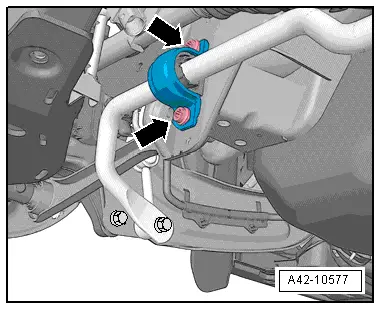
- Remove the bolts -arrows- for the stabilizer bar clamp.
- If the upper bolt for the stabilizer bar clamp cannot be removed due to the driveshaft, perform the following steps:

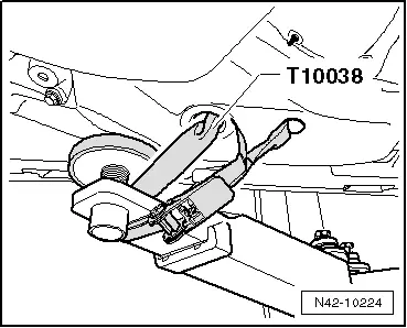
- Secure both sides of the vehicle on the hoist arms using Tensioning Straps -T10038-.
 WARNING
The vehicle could slide off the hoist if it is not secured.
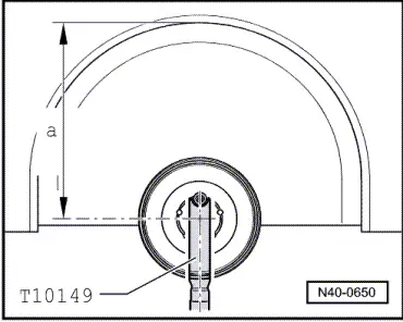
- Install Engine/Gearbox Jack Adapter - Wheel Hub Support -T10149- with wheel bolt on wheel hub.
- Lift the wheel hub using the Engine/Gearbox Jack Adapter - Wheel Hub Support -T10149- and Engine and Gearbox Jack -VAS6931- far enough until the bolts on the right stabilizer bar clamp are accessible.
- Remove the stabilizer bar.
Installing
Installation is reverse of removal, noting the following:
- Tighten the bolts -arrows- for stabilizer clamp uniformly.
- Counterhold at the inner multipoint fitting when tightening the coupling rod bolts.
- Mount the rear wheels. Refer to → Chapter "Wheels and Tires".
- An axle alignment may be required. Refer to → Chapter "Evaluating Need for Axle Alignment".
Coupling Rod, Removing and Installing
Special tools and workshop equipment required
- Torque Wrench 1331 5-50Nm -VAG1331-
Removing
- Remove the rear wheel. Refer to → Chapter "Wheels and Tires".
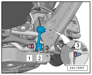
- Remove the nuts -1 and 3- and pull the coupling rod -2- out of the stabilizer bar and trailing arm.

Installing
Installation is reverse of removal, noting the following:
- Insert the coupling rod -2-, install the nuts -1 and 3- and tighten in curb weight position. Refer to → Chapter "Wheel Bearing in Curb Weight, Lifting Vehicles with Coil Spring".
- When tightening the nuts -1 and 3-, counterhold at the inner multipoint fitting of the bolts.
- Mount the rear wheel. Refer to → Chapter "Wheels and Tires".
READ NEXT:
 Overview - Transverse Link
1 - Stone Chip Protection
For allocation. Refer to the Parts Catalog.
2 - Lower Transverse Link
Removing and installing. Refer to
→ Chapter "Lower Transverse
Upper Transverse Link, Removing and Installing
Upper Transverse Link, Removing and Installing, FWD Vehicles
Special tools and workshop equipment
required
Torque Wrench 1332 40-200Nm -VAG1332-
Removing
- Measure dimension from cente
Lower Transverse Link, Removing and Installing
Lower Transverse Link, Removing and Installing, FWD Vehicles
Special tools and workshop equipment
required
Torque Wrench 1332 40-200Nm -VAG1332-
Removing
- Measure dimension from centeSEE MORE:
Map
Map function
Applies to: vehicles with navigation system
Fig. 131 Active route quidance
Fig. 132 Marked map object
Opening the map
Applies to: MMI: Press NAVIGATION on the
home screen.
If necessary, press to
display the map.
The following list gives an overview of the information
displaye
Safety precautions
Explanation of warning symbols:
Observe all warnings - there is
a risk for injury!
Always follow the instructions
in the operating manual.
Electrolyte fluid is highly
corrosive. Always wear protective gloves and eye protection.
First aid: if electrolyte fluid enters the
eyes, immediately flus