Audi Q3: Evaporator, Removing and Installing
Removing
- Removing the air distribution housing. Refer to → Chapter "Air Distribution Housing, Removing and Installing".
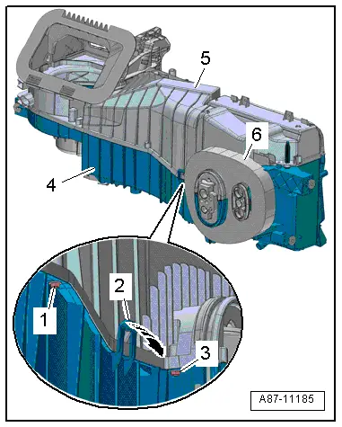
- Remove the spacer foam -6-.
- Remove the bolts -1 and 3-.
- Remove the air distribution housing upper section -5- from the lower section -4- by releasing the retainers -2--arrow-.
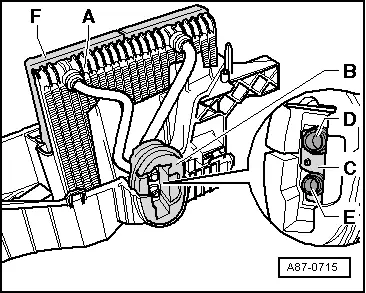
- Remove the evaporator -A- from the evaporator housing lower section.
- Remove the expansion valve. Refer to → Chapter "Expansion Valve, Removing and Installing".
- Remove the seal/insulation -B- by pulling the moving part to the side.
- Remove the retaining plate -C- for the refrigerant lines.
Installing
Installation is done is reverse order, observe the following:
- Clean the air guide housing lower section and the condensation water drain before inserting the evaporator.
- The seal -F- attached to the evaporator must be bonded all around - check for damage.
- Replace the O-ring seals. For the correct version, refer to the Parts Catalog.
- Insert the O-ring seals on the connection pipes -D and E- to the evaporator.
 Note
Note
- The expansion valve is available in different versions (same housing but a different control characteristic). Therefore, to ensure the exact allocation, refer to the Parts Catalog.
- Coat the O-ring seals lightly with refrigerant oil prior to installation. Refer to → Chapter "Refrigerant Circuit Seals".
- Inspect the refrigerant pipes leading to the evaporator for debris and damage.
- Check O-ring seals for proper seating on evaporator connecting pipes.
- If the heat protection insulation -2- is missing or not installed correctly, it can cause reduced output of the A/C system (change of the set control characteristic due to radiant heat).
Evaporator, Cleaning
Special tools and workshop equipment required
- Ultrasound A/C Cleaner -VAS6189B-
- Ultrasound A/C Cleaner - Airco-Clean Fluid -VAS6189/1-
- Suction Nozzle With Brush -VAS6288-
- Commercially available vacuum cleaner
Procedure
- Check by changing from fresh air mode to recirculating air mode to see whether the odor is actually originating from the A/C unit evaporator. Refer to → Chapter "Odors in Vehicles with A/C System".
- Check the plenum chamber water drain and clean if necessary. Refer to → Chapter "Plenum Chamber Water Drain, Checking".
- Remove the dust and pollen filter. Refer to → Chapter "Dust and Pollen Filter, Removing and Installing".
- Clean the installation shaft for the dust and pollen filter.
- Close the opening on the A/C unit for the dust and pollen filter.
- Start the engine.
- Close the windows, sunroof and rear lid.
- Open all instrument panel vents.
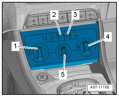
Vehicles with Manually Controlled A/C System:
- Set the airflow direction to "instrument panel vents" via the air distribution knob -4-.
- Switch on the "recirculating air mode" on the A/C Control Module -J301- control head and switch off the A/C compressor.
- The indicator lamp in the button -3- illuminates.
- The indicator lamp in the button -2- does not illuminate.
- Set the lowest temperature possible.
- Temperature knob -1- at the "cold" stop.
- Set the level "1" on the fresh-air blower knob -5-.
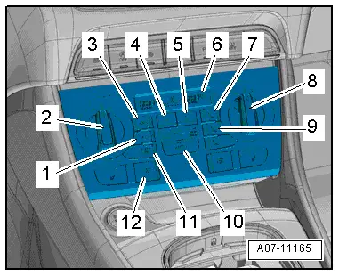
Vehicles with Automatic Climate Control System:
- Switch on the "recirculating air mode" on the Climatronic Control Module -J255- control head and switch off the A/C compressor.
- The indicator lamp in the button -3- illuminates.
- The indicator lamp in the button -1- does not illuminate.
- Set the lowest temperature possible.
- Temperature preset via the knobs -2 and 8- - "LO" for the driver and front passenger side in the display -6- on the Climatronic Control Module -J255-.
- Set the airflow direction to "instrument panel vents" via the air distribution button -9-.
- Set the lowest blower speed via the fresh air blower button -4- (the Fresh Air Blower -V2- runs at the lowest speed).
For all Vehicles:
- Shake the bottle of Ultrasound A/C Cleaner - Airco-Clean Fluid -VAS6189/1- and pour it into the Ultrasound A/C Cleaner -VAS6189B-.
 Note
Note
For using the ultrasound A/C cleaner, refer to the Parts Catalog.
- Place the Ultrasound A/C Cleaner -VAS6189B- in the front passenger footwell.
- Start the Ultrasound A/C Cleaner -VAS6189B- (according to the operating instructions) and route outlet hose belonging to it so vapor escaping via A/C unit recirculated air opening (in passenger footwell behind the glove compartment) is drawn in by the Fresh Air Blower -V2-.
- Close the vehicle doors.
 Note
Note
The cleaning procedure lasts about 15 to 20 minutes. It is complete when vapor no longer comes out of the outlet hose of the Ultrasound A/C Cleaner -VAS6189B-.
- Switch off the Ultrasound A/C Cleaner -VAS6189B-.
- Open the vehicle doors and air it out for at least 10 minutes.
- Remove the Ultrasound A/C Cleaner -VAS6189B- and clean it.
- Turn off the ignition.
- Install the dust and pollen filter. Refer to → Chapter "Dust and Pollen Filter, Removing and Installing".
READ NEXT:
 Auxiliary Heater Heating Element -Z35-, Checking
Note
An auxiliary heater is currently installed in vehicles with
a TDI engine. After leaving the heater core for the heater/A/C
unit, the air is supplied with heat energy on this syst
Heater and A/C Unit, Removing and Installing
Special tools and workshop equipment
required
Hose Clamps - Up To 25mm -3094-
Engine Bung Set -VAS6122-
Compressed air gun, commercially available
Removing
WARNING
There is a
Air Distribution Housing, Removing and Installing
Removing
- Remove the Air Conditioning (A/C) unit (heater). Refer to
→ Chapter "Heater and A/C Unit, Removing and Installing".
- Remove the bolts -arrows-.
- Remove the heate
SEE MORE:
Adding engine oil
Fig. 149 Engine compartment: engine oil filling opening
cover (example)
Observe the safety precautions.
Turn the engine off.
Open the hood.
Unscrew the cap for the
engine oil filler
opening fig. 149.
Carefully add 0.5 quart (0.5 liter) of the correct
oil.
Check the oil level again after
Stabilizer Bar, Removing and Installing
Special tools and workshop equipment
required
Locating Pins -T10096-
Torque Wrench 1332 40-200Nm -VAG1332-
Engine and Gearbox Jack -VAS6931-
Puller - Ball Joint -3287A-
Removing
- Remove the footwell trim panel by removing the nuts
-arrows-.
- Remove the bolt -arrow- fr
