Audi Q3: Stabilizer Bar, Removing and Installing
Special tools and workshop equipment required
- Locating Pins -T10096-
- Torque Wrench 1332 40-200Nm -VAG1332-
- Engine and Gearbox Jack -VAS6931-
- Puller - Ball Joint -3287A-
Removing
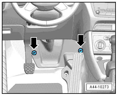
- Remove the footwell trim panel by removing the nuts -arrows-.
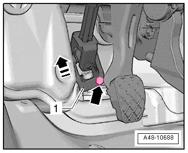
- Remove the bolt -arrow- from the universal joint -1-. Then remove the universal joint from the steering gear in direction of -arrow-.
- Remove the front wheels. Refer to → Chapter "Wheels and Tires".
- Secure the subframe. Refer to → Chapter "Subframe, Securing".
- Remove the bolts -arrows-.
- If installed, remove the Left Front Level Control System Sensor -G78- or Right Front Level Control Sensor -G289-. Refer to → Chapter "Left/Right Front Level Control System Sensor -G78-/-G289-, Removing and Installing".
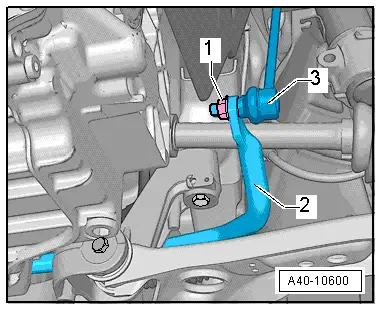
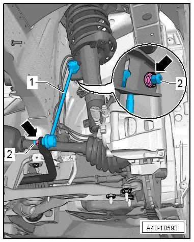
- Remove the left and right nut -1- from the coupling rod -3-.
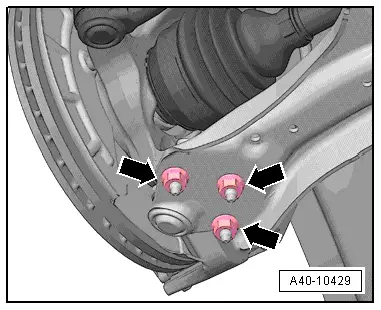
- Remove the nuts -arrows-.
- Loosen the nut of the tie rod end, but do not remove yet.
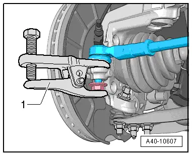
- Remove the tie rod end from the wheel bearing housing using the Puller - Ball Joint -3287A--1-.
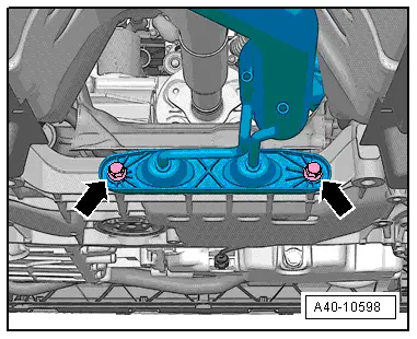
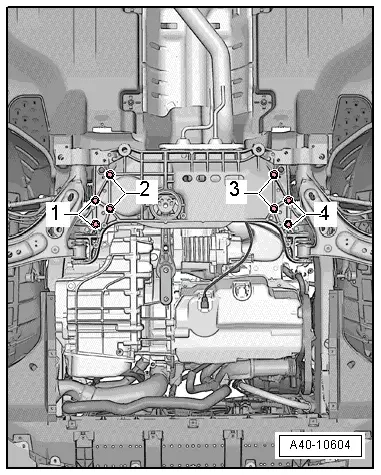
- Remove the stabilizer bar from the subframe by removing the bolts -1 and 4-.
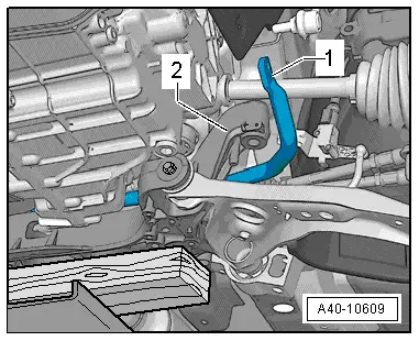
- Remove the bolts -arrows- and then remove the pendulum support from the transmission.
Vehicles with 4-cylinder Engine
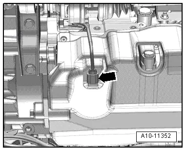
- Disconnect the connector for the Oil Level Thermal Sensor -G266--arrow- and free up the wire.
Continuation for All Vehicles
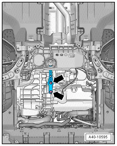
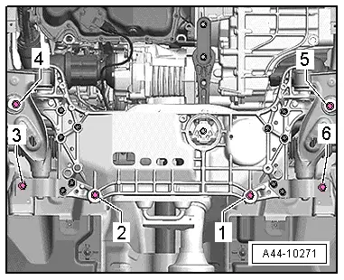
- Loosen the bolts -1- and -2- to slightly lower the subframe. Pay attention the electrical wiring while doing this.
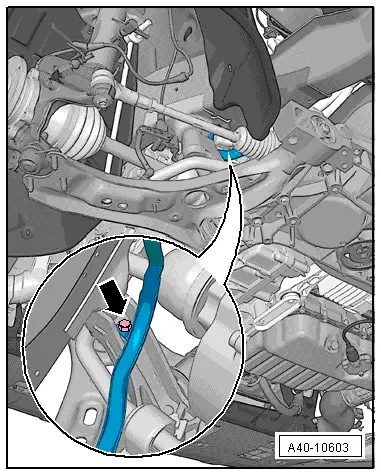
- Remove the cable guide from the subframe -arrow-.
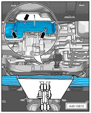
- Lower the subframe until the bolted connections -arrows- on the steering gear heat shield -1- are accessible.
- Remove the bolts -arrows- and the heat shield -1-.
- Slide the stabilizer bar toward the right, as seen in direction of travel.
- Remove the stabilizer bar -1- forward from the subframe over the console -2-.
Installing
Install in reverse order of removal while noting the following:
- Remove the Locating Pins -T10096-.
- Install the subframe with the steering gear. Refer to → Chapter "Subframe with Steering Gear, Removing and Installing".
- Install the front wheels. Refer to → Chapter "Wheels and Tires".
- An axle alignment may be required. Refer to → Chapter "Evaluating Need for Axle Alignment".
Tightening Specifications
- Pendulum support.
- Exhaust system bracket.
Coupling Rod, Removing and Installing
Special tools and workshop equipment required
- Torque Wrench 1331 5-50Nm -VAG1331-
- Torque Wrench 1331 Insert - Ring Wrench - 16mm -VAG1331/12-
Removing
- Remove the front wheel. Refer to → Chapter "Wheels and Tires".
- Remove the nuts -arrows- from the coupling rod -1- by counterholding with a multipoint socket on the threaded pin -2- if necessary.
- Remove the coupling rod -1- from the stabilizer bar and suspension strut.
- Remove the coupling rod -1-.
Installing
Installation is reverse of removal, noting the following:
- Tighten the nuts -arrow- for securing the coupling rod on the suspension strut or stabilizer bar by counterholding with a multipoint socket on the threaded pin -2-.
 Note
Note
The counter hold tool cannot be tilted.
- Install the front wheel.
READ NEXT:
 Subframe, Securing
Special tools and workshop equipment
required
Locating Pins -T10096-
Torque Wrench 1332 40-200Nm -VAG1332-
Engine and Gearbox Jack -VAS6931-
Procedure
- Remove the noise insulation
Suspension Strut and Upper Control Arm
Overview - Suspension Strut and Upper Control Arm
1 - Shock Absorber
On vehicles with electronically controlled damping, perform the
function "Adapt the control position" with the V
Overview - Lower Control Arm and Ball Joint
1 - Control Arm
Control arm with mounting bracket, removing and installing. Refer to
→ Chapter "Lower Control Arm, Removing and Installing".
2 - Bonded Rubber Bush
SEE MORE:
Roof Railing, Removing and Installing
Roof Railing, Removing and Installing
WARNING
Follow all Safety Precautions when working with
pyrotechnic components. Refer to
→ Body Interior; Rep. Gr.00; Safety Precautions; when
working with Pyrotechnic Components.
Removing
- Lower the headliner. Refer to
Map update
Introduction
Applies to: vehicles with navigation system
You can update the map data in the MMI with a
map update. The functions depend on the country
and vehicle equipment.
Map update through online map update.
Import a map update from the USB connection
to your MMI.
Online map update
Applies
