Audi Q3: Overview - Brake Booster/Master Brake Cylinder
Brake System / Chassis / Audi Q3 (8U) 2011-2018 Service Manual / Overview - Brake Booster/Master Brake Cylinder
 Note
Note
Brake master cylinder and brake boosters can be replaced independently of one another.
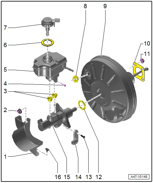
1 - Heat Shield
2 - Nut
- 25 Nm
- Always replace if removed
- Self-locking
3 - Sealing Plug
- Coat with brake fluid and press into brake fluid reservoir
4 - Bolt
- 5 Nm
5 - Brake Fluid Reservoir
- Removing and installing, refer to → Chapter "Brake Fluid Reservoir, Removing and Installing".
6 - Seal
7 - Cap
8 - Grommet
9 - Brake Booster
- Functional check:
- With engine switched off, depress brake pedal firmly several times (to exhaust the vacuum in the unit).
- Depress and hold brake pedal with average foot pressure and start engine. If brake booster is working properly, pedal will be felt to give noticeably under foot (booster assistance becomes effective).
- Disconnect from brake pedal, refer to → Chapter "Brake Pedal, Removing from Brake Booster".
- Removing and installing, refer to → Chapter "Brake Booster, Removing and Installing".
10 - Seal
- For brake booster
11 - Nut
- Tightening specification and sequence, refer to item -2-.
12 - Seal
- Replace after removing
13 - Bolt
- 5 Nm
14 - Brake Lamp Switch -F-/Brake Pedal Switch -F63-
- Removing and installing, refer to → Chapter "Brake Lamp Switch, Removing and Installing".
15 - Brake Master Cylinder
- Cannot be serviced
- If malfunctioning: replace as complete unit.
- Removing and installing, refer to → Chapter "Brake Master Cylinder, Removing and Installing".
16 - Rubber Buffer
READ NEXT:
 Brake Lamp Switch, Removing and Installing
Note
The Brake Lamp Switch -F-/Brake Pedal Switch -F63- is
installed in the brake master cylinder.
Removing
Audi RS Q3:
- Remove the air filter housing, refer to
→ Engine
Brake Master Cylinder, Removing and Installing
Special tools and workshop equipment
required
Brake Charger/Bleeder Unit -VAS5234-
Sealing plugs from Repair Kit -1H0 698 311 A-
Removing
- Remove the brake fluid reservoir,
Overview - Electric Vacuum Pump
1 - Brake System Vacuum Pump -V192-
Allocation, refer to the Parts Catalog.
Installed location: in the engine compartment over the engine
transmission separating point.
Do not diSEE MORE:
Drive system
Breaking in
A new vehicle must be broken in within the first
1,000 miles (1,500 km) so that all moving parts
work smoothly together, which helps to increase
the service life of the engine and other drive components.
Do not drive higher than two-thirds of the maximum
permitted engine RPM during the
Connector Assignments, Cell Phone Preparation Concert MOST, 9ZF
Information Electronics Control Module 1 -J794-
1 - Connector AM/FM1 from the Antenna Amplifier -R24- (Radio
Antenna 2 -R93-)
2 - DAB connection from Antenna Amplifier 4 -R113-, Digital
Radio Antenna -R183-
3 - Not installed
4 - Black connection block
© 2019-2026 Copyright www.auq3.net | 0.0097
