Audi Q3: Subframe, Servicing
Tools and Preliminary Work
Special tools and workshop equipment required
- Hydraulic Press -VAS6178-
- with Bearing Installer - Wheel Hub/Bearing Kit - Pressure Head -T10205/13- from the Bearing Installer - Wheel Hub/Bearing Kit -T10205A-
- Pneumatic/Hydraulic Foot Pump -VAS6179-
- Engine and Gearbox Jack -VAS6931-
- Tensioning Strap -T10038-
- through MY 2012 Locating Pins -T10096-
- from MY 2013 Assembly Tool, Sub-frame Alignment -T10486A-
- Subframe Bushing Assembly Tool Kit -T10356-
Subframe bonded rubber bushing, replacing, only for AWD vehicles
Procedure
- Remove the coil springs. Refer to → Chapter "Spring, Removing and Installing".
- Remove the stabilizer bar. Refer to → Chapter "Stabilizer Bar, Removing and Installing".
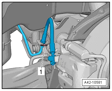
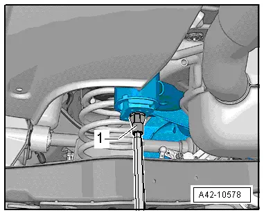
- Remove the clip -1-.
- Free up the brake line.
 Note
Note
Do not disconnect the brake line.
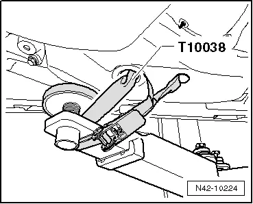
- Now secure vehicle on both sides to lifting arms on hoist with Tensioning Strap -T10038-.
 WARNING
The vehicle could slide off the hoist if it is not secured.
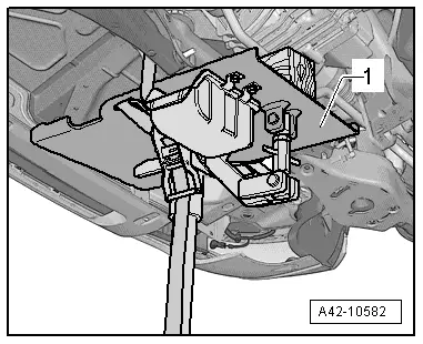
- Move the Engine and Gearbox Jack -VAS6931--1- under the subframe and secure it using the tensioning strap.
 Caution
There is a risk of damaging the subframe threaded connection threads on the body.
- The subframe bolts on the body must not be loosened or tightened with an impact wrench.
- Always install all bolts by hand for the first few turns.
- Remove the front hex bolt -1- from both sides.
 Note
Note
Only the left side of the vehicle is shown in the illustration.
To secure the subframe, the Locating Pins -T10096- (through MY 2012) must be installed at positions -1- on both sides of the vehicle one after the other. Use Assembly Tool, Sub-frame Alignment -T10486A- from MY 2013.
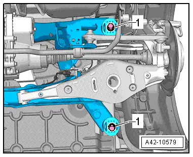
- Secure the subframe position using the locating pins -1-.
 Note
Note
The locating pins may only be tightened to a maximum of 20 Nm, since otherwise the locating pin threads will be damaged.
- Replace subframe bolts one after the other on both sides using the locating pins and tighten the locating pins to 20 Nm.
The subframe position is now secured.
- Lower the subframe 10 cm using Engine and Gearbox Jack -VAS6931-.
- Mark the installation position of bonded rubber bushing to subframe, for example, with a felt-tip pen.
Front Bonded Rubber Bushing, Servicing
Front bonded rubber bushing, removing
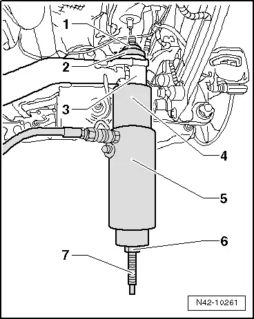
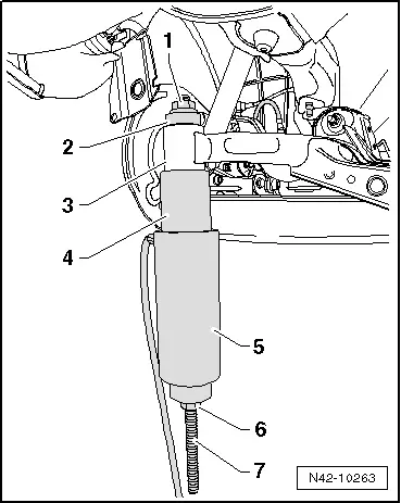
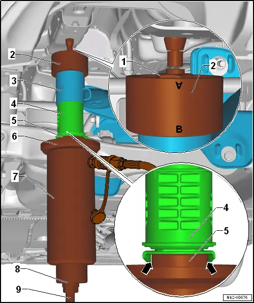
- Install special tools as depicted in the illustration.
1 - Hydraulic Press - Rear Subframe Bushing Tool Kit-Nut -T10263/5-
2 - Subframe Bushing Assembly Tool Kit-Press Piece -T10356/1-
3 - Subframe
4 - Subframe Bushing Assembly Tool Kit-Tube -T10356/2-
5 - Hydraulic Press -VAS6178- with Bearing Installer - Wheel Hub/Bearing Kit- Adapter 13 -T10205/13-
6 - Hydraulic Press - Rear Subframe Bushing Tool Kit-Nut -T10263/5-
7 - Hydraulic Press - Rear Subframe Bushing Tool Kit-Spindle -T10263/4-
- Pretension special tools.
- Pull out bonded rubber bushing by operating pump.
 Note
Note
The bearing outer race is sheared off when the bonded rubber bushing is removed. There is a loud crack when this happens.
- After removing the rubber bonded bushing, it must be removed from the Subframe Bushing Assembly Tool Kit - Tube -T10356/2-.
Installing the front bonded rubber bushing
Install in reverse order of removal. Note the following:
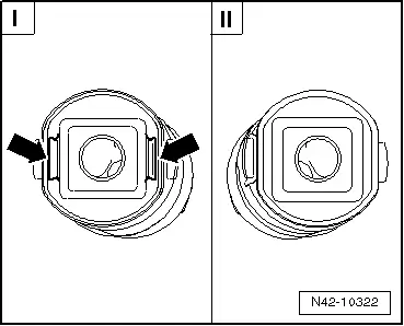
Distinguishing characteristic, rubber bonded bushing
I - Front bonded rubber bushing
II - Rear Bonded Rubber Bushing
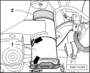
The front bonded rubber bushings have two openings -arrows- on the top and have slightly different installation heights. Refer to the Parts Catalog.
Bonded rubber bushing must be installed in the correct direction, note marking on subframe.

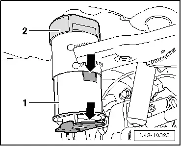
- Install the rubber bonded bushing -1- into the subframe, so that the tab and the plate -arrows- face perpendicular to direction of travel.
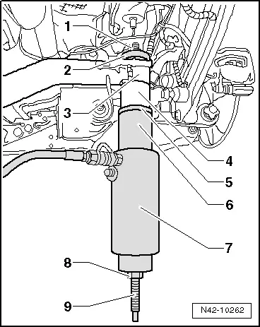
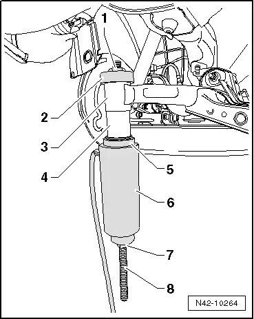
- Insert special tools with bonded rubber bushing into subframe as illustrated.
through MY 2013: Refer to Parts Catalog
1 - Hydraulic Press - Rear Subframe Bushing Tool Kit-Nut -T10263/5-
2 - Subframe Bushing Assembly Tool Kit - Guide Piece -T10356/3- with side A toward subframe
3 - Subframe
4 - Bonded Rubber Bushing
5 - Subframe Bushing Assembly Tool Kit - Press Piece -T10356/4- with side A toward bonded rubber bushing
6 - Subframe Bushing Assembly Tool Kit-Tube -T10356/2-
7 - Hydraulic Press -VAS6178- with Bearing Installer - Wheel Hub/Bearing Kit- Adapter 13 -T10205/13-
8 - Hydraulic Press - Rear Subframe Bushing Tool Kit-Nut -T10263/5-
9 - Hydraulic Press - Rear Subframe Bushing Tool Kit-Spindle -T10263/4-
From MY 2013: Refer to → Electronic Parts Catalog (ETKA)
1 - Hydraulic Press - Rear Subframe Bushing Tool Kit-Nut -T10263/5-
2 - Assembly Tool - Bushing -T10356/7- with side A toward subframe
3 - Subframe
4 - Bonded Rubber Bushing
5 - Assembly Tool - Bushing -T10356/8- with side A toward bonded rubber bushing
6 - Subframe Bushing Assembly Tool Kit-Tube -T10356/2-
7 - Hydraulic Press -VAS6178- with Bearing Installer - Wheel Hub/Bearing Kit- Adapter 13 -T10205/13-
8 - Hydraulic Press - Rear Subframe Bushing Tool Kit-Nut -T10263/5-
9 - Hydraulic Press - Rear Subframe Bushing Tool Kit-Spindle -T10263/4-
- Pretension special tool with bonded rubber bushing.
- Carefully insert bonded rubber bushing by operating pump until collar lies on subframe "without a gap".
Rear Bonded Rubber Bushing, Servicing
Pulling out rear bonded rubber bushing
- Move the Engine and Gearbox Jack -VAS6931--1- under the subframe and secure it using the tensioning strap.

 Caution
There is a risk of damaging the subframe threaded connection threads on the body.
- The subframe bolts on the body must not be loosened or tightened with an impact wrench.
- Always install all bolts by hand for the first few turns.
- Remove the rear hex bolt -1- from both sides.
 Note
Note
Only the left side of the vehicle is shown in the illustration.
To secure the subframe, the Locating Pins -T10096- (through MY 2012) must be installed at positions -1- on both sides of the vehicle one after the other. Use Assembly Tool, Subframe Alignment -T10486A- from MY 2013.

- Secure the subframe position using the locating pins.
 Note
Note
The locating pins may only be tightened to a maximum of 20 Nm, since otherwise the locating pin threads will be damaged.
- Replace subframe bolts one after the other on both sides using the locating pins and tighten the locating pins to 20 Nm.
The subframe position is now secured.
- Lower the subframe 10 cm using Engine and Gearbox Jack -VAS6931-.
- Mark the installation position of bonded rubber bushing to subframe, for example, with a felt-tip pen.

- Install special tools as depicted in the illustration.
1 - Hydraulic Press - Rear Subframe Bushing Tool Kit-Nut -T10263/5-
2 - Subframe Bushing Assembly Tool Kit - Thrust Piece-T10356/5-
3 - Subframe
4 - Subframe Bushing Assembly Tool Kit - Tube -T10356/6-
5 - Hydraulic Press -VAS6178- with Bearing Installer - Wheel Hub/Bearing Kit- Adapter 13 -T10205/13-
6 - Hydraulic Press - Rear Subframe Bushing Tool Kit-Nut -T10263/5-
7 - Hydraulic Press - Rear Subframe Bushing Tool Kit-Spindle -T10263/4-
- Pretension special tools.
- Pull out bonded rubber bushing by operating pump.
 Note
Note
The bearing outer race is sheared off when the bonded rubber bushing is removed. There is a loud crack when this happens.
- After removing the rubber bonded bushing, it must be removed from the Subframe Bushing Assembly Tool Kit - Tube -T10356/2-.
Pulling in rear bonded rubber bushing
Install in reverse order of removal. Note the following:
Distinguishing characteristic, rubber bonded bushing
I - Front bonded rubber bushing
II - Rear Bonded Rubber Bushing
The front bonded rubber bushings have two openings -arrows- on the top and have slightly different installation heights. Refer to the Parts Catalog.
Bonded rubber bushing must be installed in the correct direction, note marking on subframe.
through MY 2013: Refer to Parts Catalog
- Install the rubber bonded bushing -1- into the subframe, so that the tab and the plate -arrows- face perpendicular to direction of travel.
- Mount the Hydraulic Press - Rear Subframe Bushing Tool Kit - Pressure Piece -T10263/3--2- so that the flat side faces perpendicular to direction of travel.
- Insert special tools with bonded rubber bushing into subframe as illustrated.
1 - Hydraulic Press - Rear Subframe Bushing Tool Kit-Nut -T10263/5-
2 - Subframe Bushing Assembly Tool Kit - Guide Piece -T10356/3- with side B toward subframe
3 - Subframe
4 - Bonded Rubber Bushing
5 - Subframe Bushing Assembly Tool Kit - Press Piece -T10356/4- with side B toward bonded rubber bushing
6 - Hydraulic Press -VAS6178- with Bearing Installer - Wheel Hub/Bearing Kit- Adapter 13 -T10205/13-
7 - Hydraulic Press - Rear Subframe Bushing Tool Kit-Nut -T10263/5-
8 - Hydraulic Press - Rear Subframe Bushing Tool Kit-Spindle -T10263/4-
From MY 2013: Refer to Parts Catalog
- Insert special tools with bonded rubber bushing into subframe as illustrated.
1 - Hydraulic Press - Rear Subframe Bushing Tool Kit - Nut -T10263/5-
2 - Assembly Tool - Bushing -T10356/7- - the marking -B- points to the subframe
3 - Subframe
4 - adjust the bonded rubber bushing to the marks (the marks need to align)
5 - Assembly Tool - Bushing -T10356/8- - the flattened sides need to fit into the cover of the bonded rubber bushing -arrows-.
6 - Bearing Installer - Wheel Hub/Bearing Kit - Gripping Device -T10205/1-
7 - Hydraulic Press -VAS6178- with Bearing Installer - Wheel Hub/Bearing Kit Pressure Head -T10205/13-
8 - Hydraulic Press - Rear Subframe Bushing Tool Kit - Nut -T10263/5-
9 - Hydraulic Press - Rear Subframe Bushing Tool Kit - Threaded Rod -T10263/4-
- Pretension special tool with bonded rubber bushing.
- Carefully insert bonded rubber bushing by operating pump until collar lies on subframe "without a gap".
Install in reverse order of removal.
- Install the coil springs. Refer to → Chapter "Spring, Removing and Installing".
- An axle alignment may be required. Refer to → Chapter "Evaluating Need for Axle Alignment".
READ NEXT:
 Stabilizer Bar
Overview - Stabilizer Bar
1 - Subframe
2 - Bolt
25 Nm + 45º
Always replace if removed
Install evenly
3 - Clamp
4 - Bearing
Always replace t
Overview - Transverse Link
1 - Stone Chip Protection
For allocation. Refer to the Parts Catalog.
2 - Lower Transverse Link
Removing and installing. Refer to
→ Chapter "Lower Transverse
Upper Transverse Link, Removing and Installing
Upper Transverse Link, Removing and Installing, FWD Vehicles
Special tools and workshop equipment
required
Torque Wrench 1332 40-200Nm -VAG1332-
Removing
- Measure dimension from cente
SEE MORE:
Inner Door Seal, Removing and Installing
Removing
- Remove the rear sill panel strip. Refer to
→ Body Interior; Rep. Gr.70; Passenger Compartment Trim; Sill
Panel Strip, Removing and Installing.
- Remove the upper and lower B-pillar trim. Refer to
→ Body Interior; Rep. Gr.70; Passenger Comp
Electrical system
The following messages may appear depending
on the vehicle equipment:
If the or
indicator light turns on, there is
a
malfunction in the generator, the battery, or the
vehicle electrical system.
Electrical system:
malfunction! Safely stop
vehicle
or
Electrical system:
malfunction! Battery is
n
