Audi Q3: Suspension Strut/Shock Absorber, Spring
Overview - Suspension Strut, Shock Absorber and Spring
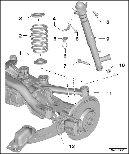
1 - Lower Spring Support
- Spring end rotated up to stop
2 - Coil Spring
- Removing and installing. Refer to → Chapter "Spring, Removing and Installing".
3 - Upper Spring Support
4 - Bracket for Rear Body Acceleration Sensor -G343-
- Installed on a vehicle with electronic damping
5 - Rear Body Acceleration Sensor -G343-
- Removing and installing. Refer to → Chapter "Rear Body Acceleration Sensor -G343-, Removing and Installing".
- Installed on a vehicle with electronic damping
6 - Bolt
- 5 Nm
- Installed on a vehicle with electronic damping
7 - Bolt
- 180 Nm
- Always replace if removed
8 - Bolt
- 50 Nm + 45º
- Always replace if removed
9 - Shock Absorber
- Removing and installing. Refer to → Chapter "Shock Absorber, Removing and Installing".
- Always release gas and drain malfunctioning shock absorbers before disposal. Refer to → Chapter "Rear Shock Absorbers, Venting and Emptying".
- On vehicles with electronically controlled damping, perform the function "Adapt the control position" with the Vehicle Diagnosis Tester.
- If the control position was reprogrammed and if the vehicle has lane assist, then it will then be necessary to calibrate the driver assistance systems front camera. Refer to → Chapter "Driver Assistance Systems Front Camera, Calibrating".
- On vehicles with level control system sensor, perform headlamp basic setting. Refer to → Electrical Equipment; Rep. Gr.94; Headlamp, Adjusting.
10 - Washer
11 - Subframe
12 - Wheel Bearing Housing
Shock Absorber, Removing and Installing
Special tools and workshop equipment required
- Torque Wrench 1332 40-200Nm -VAG1332-
Removing
- Measure dimension from center of wheel to lower edge of wheel housing. Refer to → Chapter "Wheel Bearing in Curb Weight, Lifting Vehicles with Coil Spring".
- Remove the wheel housing liner. Refer to → Body Exterior; Rep. Gr.66; Wheel Housing Liner; Rear Wheel Housing Liner, Removing and Installing.
- Remove the coil spring. Refer to → Chapter "Spring, Removing and Installing".
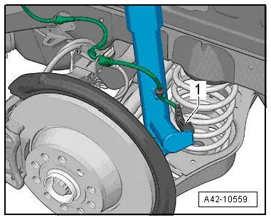
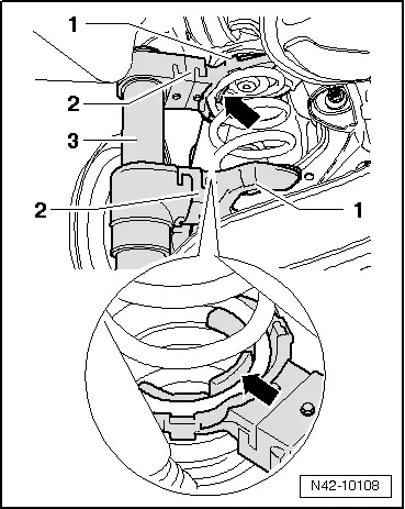
- If installed, disconnect the connector -1- and free up the wire on the shock absorber.
- Remove the bolts -arrows-.
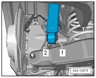
- If installed, remove the Rear Body Acceleration Sensor -G343--1- from the shock absorber mount.
- Remove the bolt -1- and the washer -2-.
- Remove shock absorber.
Installing
Install in reverse order of removal. Note the following:
Fastening the shock absorber to the wheel bearing housing may only occur after the dimension measured before assembly between the wheel hub center and the lower edge of wheel housing has been attained. Refer to → Chapter "Wheel Bearing in Curb Weight, Lifting Vehicles with Coil Spring".
Note the shock absorber installation position.
The Left and Right Rear Dampening Adjustment Valve -N338/N339- must point toward the outside of the rear wheel.
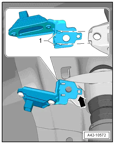
- For vehicles with electronic damping, position the Rear Body Acceleration Sensor -G343- on the shock absorber mount.
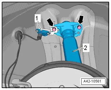
- Mount the bracket on the shock absorber mount from the rear, so that the bracket tabs -1- engage in the recesses on the shock absorber mount.
- Turn the bracket forward so that it contacts the shock absorber mount.
The tab -arrow- is used for adjusting the Rear Body Acceleration Sensor -G343- bracket.
- Install the coil spring. Refer to → Chapter "Spring, Removing and Installing".
- An axle alignment may be required. Refer to → Chapter "Evaluating Need for Axle Alignment".
- On vehicles with electronically controlled damping, perform the function "Adapt the control position" with the → Vehicle diagnostic tester.
- If the control position was reprogrammed and if the vehicle has lane assist, then it will then be necessary to calibrate the driver assistance systems front camera. Refer to → Chapter "Driver Assistance Systems Front Camera, Calibrating".
- On vehicles with level control system sensor, perform headlamp basic setting. Refer to → Electrical Equipment; Rep. Gr.94; Headlamp, Adjusting.
Shock Absorber, Servicing
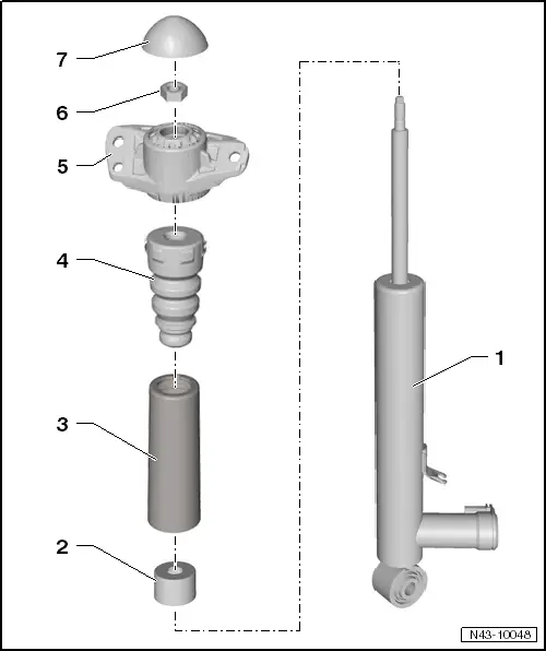
1 - Shock Absorber
- Removing and installing. Refer to → Chapter "Shock Absorber, Removing and Installing".
- Always release gas and drain malfunctioning shock absorbers before disposal. Refer to → Chapter "Rear Shock Absorbers, Venting and Emptying".
- Shock Absorber, Checking. Refer to → Chapter "Shock Absorbers, Checking when Removed".
- On vehicles with electronically controlled damping, perform the function "Adapt the control position" with the Vehicle Diagnostic Tester.
- If the control position was reprogrammed and if the vehicle has lane assist, then it will then be necessary to calibrate the driver assistance systems front camera. Refer to → Chapter "Driver Assistance Systems Front Camera, Calibrating".
- On vehicles with level control system sensor, perform headlamp basic setting. Refer to → Electrical Equipment; Rep. Gr.94; Headlamp, Adjusting.
2 - Protective Cap
3 - Protective Pipe
4 - Stop Buffer
5 - Shock Absorber Mount
6 - Nut
- 25 Nm
- Always replace if removed
- Loosening and tightening. Refer to
7 - Cover
Special tools and workshop equipment required
- Torque Wrench 1332 40-200Nm -VAG1332-
- Shock Absorber Set -T10001-
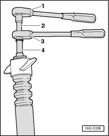
Loosening and tightening bolted connection for shock absorber mount
1 - Ratchet (commercially available)
2 - Shock Absorber Set - Socket -T10001/9-
3 - Shock Absorber Set - Reversible Ratchet -T10001/11-
4 - Shock Absorber Set - Socket -T10001/1-
Install in reverse order of removal. Note the following:
Tightening specification: refer to -item 6-.
Spring, Removing and Installing
Special tools and workshop equipment required
- Spring Compressor Kit - Spring Tensioner -VAG1752/1-
- Spring Compressor Kit - Spring Retainer w/Inserts -VAG1752/3A-
- Spring Compressor Kit - Adapter Blocks -VAG1752/9-, not illustrated
Removing
- Remove the rear wheel. Refer to → Chapter "Wheels and Tires".
- Insert the spring tensioner -3-.
 WARNING
Make sure that coil spring is seated correctly in the Spring Compressor Kit - Spring Retainer w/Inserts -VAG1752/3A--2- (danger of accident).
- Compress coil spring until it can be removed.
- Remove spring.
1 - Spring Compressor Kit - Spring Retainer w/Inserts -VAG1752/3A-
2 - Spring Compressor Kit - Adapter Blocks -VAG1752/9-
3 - Spring Compressor Kit - Spring Tensioner -VAG1752/1-
Installing
Installation is reverse of removal, noting the following:
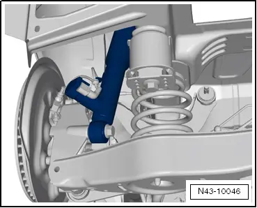
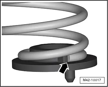
The spring start -arrow- must touch the stop of lower spring support.
- Insert the spring together with the spring support.
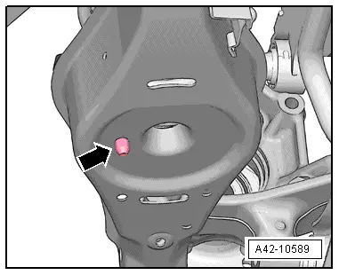
- The spring seat has a pin on bottom.
- Insert this pin into hole of lower control arm -arrow-.
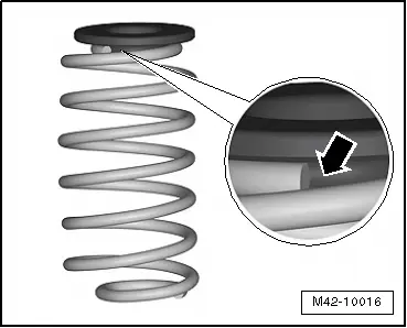
- Insert the top of the spring support into the upper spring end.
- Tension spring. For this, place the upper spring support on the body tab.
- Remove the spring tensioner.
- Mount the rear wheel. Refer to → Chapter "Wheels and Tires".
- An axle alignment may be required. Refer to → Chapter "Evaluating Need for Axle Alignment".
If one or more springs are replaced:
- On vehicles with electronically controlled damping, perform the function "Adapt the control position" with the Vehicle Diagnosis Tester.
- If the control position was reprogrammed and if the vehicle has lane assist, then it will then be necessary to calibrate the driver assistance systems front camera. Refer to → Chapter "Driver Assistance Systems Front Camera, Calibrating".
- On vehicles with level control system sensor, perform headlamp basic setting. Refer to → Electrical Equipment; Rep. Gr.94; Headlamp, Adjusting.
READ NEXT:
 Overview - Wheel Bearing
Overview - Wheel Bearing, Vehicles with FWD
1 - Cover
2 - Bracket
3 - Bolt
50 Nm + 45º
Always replace if removed
4 - Coupling Rod
5 -
Wheel Bearing Housing, Removing and Installing
Wheel Bearing Housing, Removing and Installing, FWD Vehicles
Special tools and workshop equipment
required
Torque Wrench 1332 40-200Nm -VAG1332-
Removing
- Measure dimension from cente
Wheel Bearing Unit, Removing and Installing
Wheel Bearing Unit, FWD, Removing and Installing
Special tools and workshop equipment
required
Puller - Grease Cap -VW637/2-
Camshaft Installer Kit - Sleeve -3241/4- from the Seal
Installer
SEE MORE:
Wheel Bearing Housing, Removing and Installing
Special tools and workshop equipment
required
Puller - Ball Joint -3287A-
Torque Wrench 1332 40-200Nm -VAG1332-
Engine and Gearbox Jack -VAS6931-
Digital Torque Wrench -VAG1756A-
Spreader Tool -3424-
Removing
- Loosen the drive axle threaded connection on the wheel side.
Ref
Left/Right Headlamp Beam Adjustment Motor -V48-/-V49-, Removing and
Installing
Left/Right Headlamp Beam Adjustment Motor -V48-/-V49-, Removing and
Installing, Halogen Headlamps
Removing
- Remove the headlamp housing. Refer to
→ Chapter "Headlamp, Removing and Installing, Halogen Headlamps".
- If equipped, remove the bolts -1 and
3-.
- Open the t
