Audi Q3: Overview - Subframe
Suspension, Wheels, Steering / Chassis / Audi Q3 (8U) 2011-2018 Service Manual / Overview - Subframe
 Caution
There is a risk of damaging the subframe threaded connection threads on the body.
- The subframe bolts on the body must not be loosened or tightened with an impact wrench.
- Always install all bolts by hand for the first few turns.
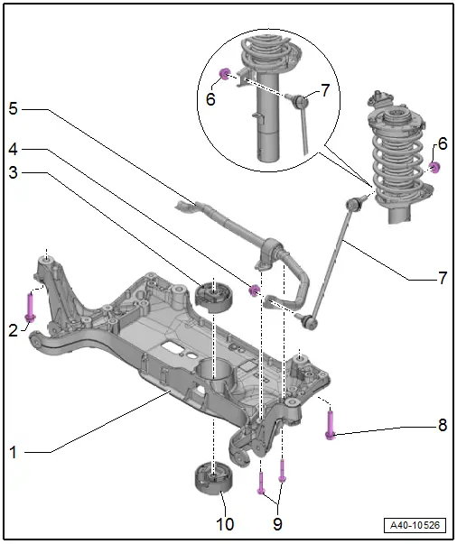
1 - Subframe
- Securing. Refer to → Chapter "Subframe, Securing".
- Lowering. Refer to → Chapter "Subframe, Lowering".
- Removing and installing without steering gear. Refer to → Chapter "Subframe without Steering Gear, Removing and Installing".
- Removing and installing with steering gear. Refer to → Chapter "Subframe with Steering Gear, Removing and Installing".
2 - Bolt
- 70 Nm +180º
- Always replace if removed
3 - Upper Bonded Rubber Bushing for Pendulum Support
- Replacing. Refer to → Chapter "Subframe, Servicing".
4 - Nut
- 65 Nm
- Always replace if removed
- Counterhold at socket head of joint bolt when tightening
5 - Stabilizer Bar
- Removing and installing. Refer to → Chapter "Stabilizer Bar, Removing and Installing".
6 - Nut
- 65 Nm
- Always replace if removed
- Counterhold at socket head of joint bolt when tightening
7 - Coupling Rod
- Removing and installing. Refer to → Chapter "Coupling Rod, Removing and Installing".
8 - Bolt
- 70 Nm +180º
- Always replace if removed
9 - Bolts
- 20 Nm +90º
- Always replace if removed
10 - Lower Bonded Rubber Bushing for Pendulum Support
- Replacing. Refer to → Chapter "Subframe, Servicing".
READ NEXT:
 Subframe without Steering Gear, Removing and Installing
Special tools and workshop equipment
required
Torque Wrench 1331 5-50Nm -VAG1331-
Torque Wrench 1332 40-200Nm -VAG1332-
Engine and Gearbox Jack -VAS6931-
Removing
Note
Subframe
Subframe, Servicing
Special tools and workshop equipment
required
Bearing Installer - Wheel Hub/Bearing Kit -T10205-
Torque Wrench 1332 40-200Nm -VAG1332-
Hydraulic Press -VAS6178-
Pneumatic/Hydraulic Foot Pu
Stabilizer Bar, Removing and Installing
Special tools and workshop equipment
required
Locating Pins -T10096-
Torque Wrench 1332 40-200Nm -VAG1332-
Engine and Gearbox Jack -VAS6931-
Puller - Ball Joint -3287A-
Removing
- SEE MORE:
Additional safety belt functions
Belt retractor lock
The safety belts on the rear seats and on the
front passenger seat are equipped with a belt retractor
lock.
If you secure a child safety seat with a safety
belt, the belt retractor lock on the safety belt
may need to be activated. Follow the instructions
from the child safet
Surrounding area detection
Sensor and camera coverage areas
Fig. 88 Sensor coverage area
Fig. 89 Rearview camera coverage area
The assist systems analyze the data from various
sensors and cameras installed in the vehicle. Do
not use any assist systems if there is damage in
there area of the sensors and cameras or on the
veh
© 2019-2026 Copyright www.auq3.net | 0.0114
