Audi Q3: Subframe, Servicing
Special tools and workshop equipment required
- Bearing Installer - Wheel Hub/Bearing Kit -T10205-
- Torque Wrench 1332 40-200Nm -VAG1332-
- Hydraulic Press -VAS6178-
- Pneumatic/Hydraulic Foot Pump -VAS6179-
- Hydraulic Press - Bushing Tool Kit -VAS6779-
- Press Plate -VW401-
- Press Piece - Multiple Use -VW412-
Replace the pendulum support bonded rubber bushing.
- Remove the front noise insulation. Refer to → Body Exterior; Rep. Gr.66; Overview - Noise Insulation.
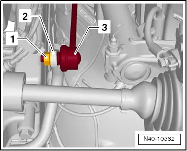
- Remove the hex nut -1- from the right and left coupling rod -3-.
- Remove the coupling rod -3- from the stabilizer bar -2- on the left and right sides.
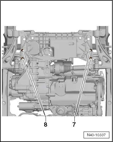
- Remove the stabilizer bolts -7- and -8-.
- Leave the stabilizer bar in the installed position on the vehicle.
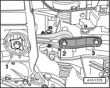
- Remove the bolt -1-.
- Remove the bolts -2- and -3-.
- Remove the pendulum support.
Pressing out the bonded rubber bushing
- Install the Hydraulic Press - Bushing Tool Kit -VAS6779 -as shown in the illustration on the subframe.
- Position the Hydraulic Press - Bushing Tool Kit -Thrust Piece -VAS6779-1--1- with the flat side -arrow- on the bonded rubber bushing in the driving direction.
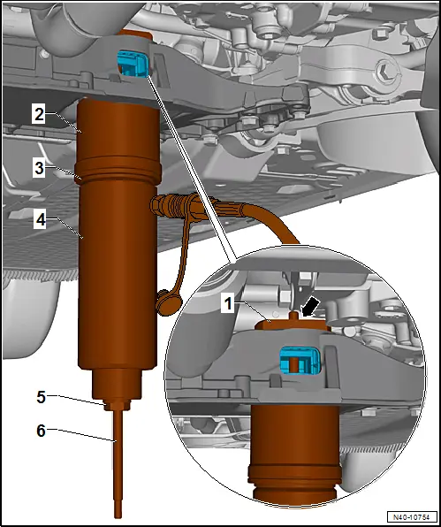
1 - Hydraulic Press - Bushing Tool Kit -Thrust Piece -VAS6779/1-
2 - Hydraulic Press - Bushing Tool Kit -Tube -VAS6779/4-, with the small outer diameter to the sub frame.
3 - Hydraulic Press - Bushing Tool Kit -Thrust Piece -VAS6779/5-
4 - Hydraulic Press -VAS6178- with Bearing Installer - Wheel Hub/Bearing Kit Pressure Head -T10205/13-
5 - Hydraulic Press - Bushing Tool Kit -Hexagon Nut -VAS6779/3-
6 - Hydraulic Press - Bushing Tool Kit -Threaded Rod -VAS6779/2-
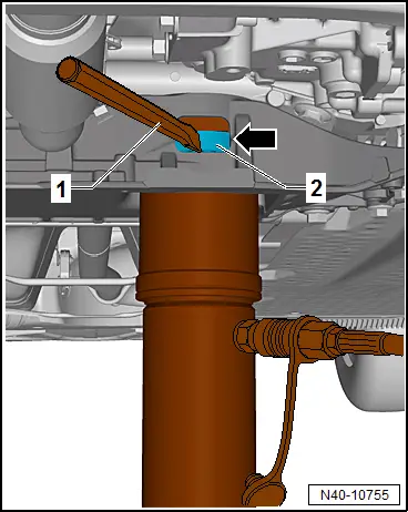
- Press out both bonded rubber bushings until the upper bonded rubber busing -2- is visible through the opening for the pendulum support -arrow- in the subframe.
- Perform a visual inspection of the upper bonded rubber bushing -2- outer race.
- If the upper bonded rubber bushing -2- outer race is deformed, it must be destroyed through the opening for the pendulum support -arrow- in the subframe.
- Using a using a chisel or similar tool -1-, make a break in the upper bonded rubber bushing -2- outer race.
 Note
Note
This work sequence is necessary to prevent tilting of the bonded rubber bushing outer race in the area of the pendulum support opening in the subframe.
- Completely press out both bonded rubber bushings at the same time.
Prepare the bonded rubber bushing before pressing in.
 Note
Note
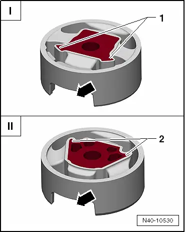
- There are two different versions of the pendulum support bonded rubber bushing: the T version -I- and the V version -II-.
- For the correct allocation. Refer to the Parts Catalog.
I - The corners on the inner core -1- face toward the opening for the pendulum support -arrow- (T version).
II - The corners on the inner core -2- face away from the opening for the pendulum support -arrow- (V version).
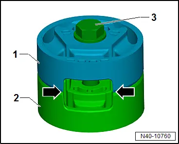
- Place the bonded rubber bushings -1- and -2- on top of each other so the openings -arrows- lay exactly over each other.
- Tighten the bonded rubber bushings -1- and -2- using the original bolt -3- hand tight.
- Place the bonded rubber busing -1- with the bolt head facing up in the larger diameter of the Hydraulic Press - Bushing Tool Kit - Funnel -VAS6779/6--2-.
- Align the bonded rubber busing -1- in the Hydraulic Press - Bushing Tool Kit - Funnel -VAS6779/6--2-. The bonded rubber bushing opening -arrows- must exactly lay in the recess on the Hydraulic Press - Bushing Tool Kit - Funnel -VAS6779/6--2-.
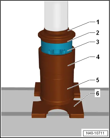
- Press the bonded rubber bushing -3- in the Hydraulic Press - Bushing Tool Kit - Funnel -VAS6779/6- as shown in the illustration until stop.
1 - Press Piece - Multiple Use -VW412-
2 - Hydraulic Press - Bushing Tool Kit -Thrust Piece -VAS6779/5-, the side with the letter "A" points up
3 - Bonded Rubber Bushing
4 - Funnel -VAS6779/6-
5 - Tube -VAS6779/4-
6 - Press Plate -VW401-
- Remove the bolt from the bonded rubber bushing.
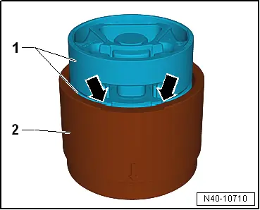
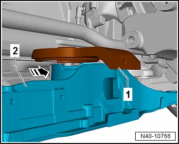
- Place the Hydraulic Press - Bushing Tool Kit-Counter Hold -VAS6779/7--1- front left in the direction of the-arrow- on the subframe -2-.
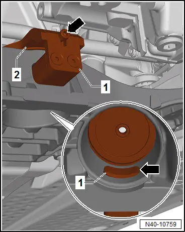
- Insert the Insert -VAS6779/7-1A--1- in the pendulum support opening in the subframe.
- Attach the Insert -VAS6779/7-1A- with the bolt -arrow- on the Hydraulic Press - Bushing Tool Kit-Counter Hold -VAS6779/7--2-.
- Pay attention that the Insert -VAS6779/7-1A--1- is seated correctly in the subframe opening -arrow-.
Installing the bonded rubber bushing
- Install the Hydraulic Press - Bushing Tool Kit -Threaded Rod -VAS6779/2--7- in the Hydraulic Press - Bushing Tool Kit-Counter Hold -VAS6779/7--1-.
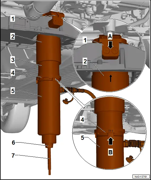
- Install the Hydraulic Press - Bushing Tool Kit -VAS6779- as shown in the illustration on the subframe.
1 - Hydraulic Press - Bushing Tool Kit-Counter Hold -VAS6779/7-
2 - Hydraulic Press - Bushing Tool Kit - Funnel -VAS6779/6-, -arrow marking- on the funnel must be opposite of both bolts -arrow A-.
3 - Hydraulic Press - Bushing Tool Kit - Thrust Piece -VAS6779/9-
4 - Hydraulic Press - Bushing Tool Kit -Incremental Ring -VAS6779/8-, the marking -IIII- on the Incremental Ring must point to the cam -arrow B- on the Hydraulic Press - Bushing Tool Kit -Thrust Piece -VAS6779/9-.
5 - Hydraulic Press -VAS6178- with Bearing Installer - Wheel Hub/Bearing Kit Pressure Head -T10205/13-
6 - Hydraulic Press - Bushing Tool Kit - Hexagon Nut -VAS6779/3-
7 - Hydraulic Press - Bushing Tool Kit - Threaded Rod -VAS6779/2-
- Press in both bonded rubber busing at the same time.
- Remove Hydraulic Press - Bushing Tool Kit -VAS6779- from the subframe and check seating of the pressed in bonded rubber bushing.
- Fasten the stabilizer bar with the subframe and the coupling rod.
- Install the pendulum support.
- Install the front noise insulation. Refer to → Body Exterior; Rep. Gr.66; Overview - Noise Insulation.
Tightening Specifications
- Pendulum support.
READ NEXT:
 Stabilizer Bar, Removing and Installing
Special tools and workshop equipment
required
Locating Pins -T10096-
Torque Wrench 1332 40-200Nm -VAG1332-
Engine and Gearbox Jack -VAS6931-
Puller - Ball Joint -3287A-
Removing
-
Subframe, Securing
Special tools and workshop equipment
required
Locating Pins -T10096-
Torque Wrench 1332 40-200Nm -VAG1332-
Engine and Gearbox Jack -VAS6931-
Procedure
- Remove the noise insulation
Suspension Strut and Upper Control Arm
Overview - Suspension Strut and Upper Control Arm
1 - Shock Absorber
On vehicles with electronically controlled damping, perform the
function "Adapt the control position" with the VSEE MORE:
Engine oil
If the engine oil level is too low
Fig. 147 Engine oil sticker
Engine oil viscosity
Engine oil standard
If you need to add engine oil, use an oil that
meets the engine oil standard listed on the sticker
fig. 147. The sticker with the
specified
standard is located in the front of the engine co
Overview - Wheel Bearing
1 - Suspension Strut
2 - Bolt
70 Nm + 90º
Always replace if removed
Bolt point must face in direction of travel.
3 - Front Speed Sensor
Removing and installing. Refer to
→ Brake System; Rep. Gr.45; Sensors; Front ABS Wheel Speed Sen