Audi Q3: Subframe without Steering Gear, Removing and Installing
Special tools and workshop equipment required
- Torque Wrench 1331 5-50Nm -VAG1331-
- Torque Wrench 1332 40-200Nm -VAG1332-
- Engine and Gearbox Jack -VAS6931-
Removing
 Note
Note
Subframe is removed together with control arms.
- Remove the front wheels. Refer to → Chapter "Wheels and Tires".
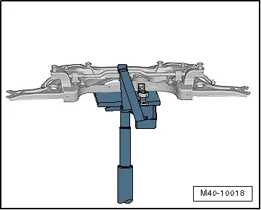
- Secure the subframe. Refer to → Chapter "Subframe, Securing".
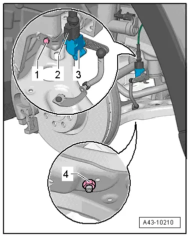
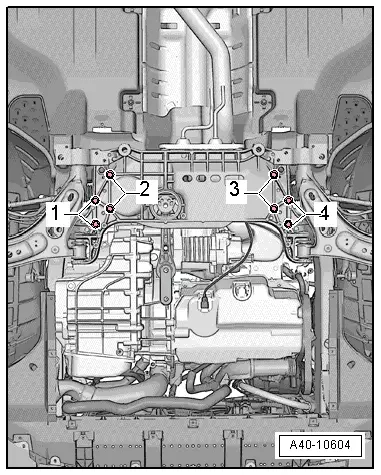
- If installed, disconnect the connector -2- from the Left Front Level Control System Sensor -G78- or Right Front Level Control Sensor -G289-.
- Remove the nut -4- and free up the coupling rod from the Left Front Level Control System Sensor -G78- or Right Front Level Control Sensor -G289-.
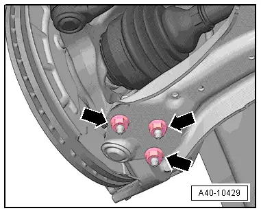
- Remove the nuts -arrows- on left and right side of vehicle.
- Remove the control arm from the ball joint.
 Note
Note
Pay attention during the assembly work that the ball joint rubber boot is not damaged. If necessary protect the ball joint rubber boot against damage.
Vehicles with 4-cylinder Engine
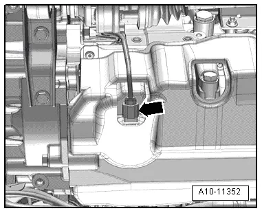
- Disconnect the connector for the Oil Level Thermal Sensor -G266--arrow- and free up the wire.

Continuation for All Vehicles
- Remove the bolts -arrows-.
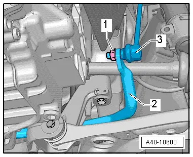
- Remove the left and right nut -1- from the coupling rod -3-.
- Remove the coupling rod -3- from the stabilizer bar -2- on the left and right sides.

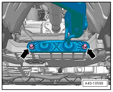
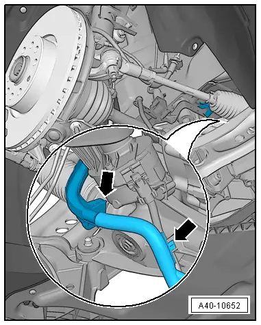
- Remove the bolts -arrows- and then remove the pendulum support from the transmission.
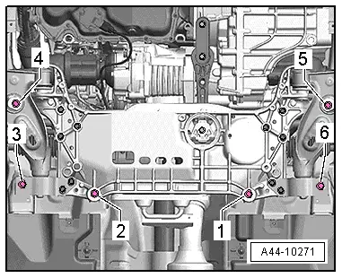
- Remove the steering gear bolts -2- and -3-.
- Remove the stabilizer bar bolts -1- and -4-.
- Remove the subframe bolts -1 through 6-.
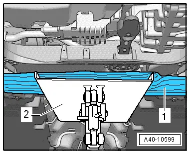
- Slightly lower the subframe using the Engine and Gearbox Jack -VAS6931--2-.
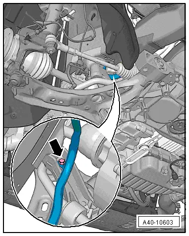
- Remove the cable guide from the subframe -arrow-.
- Secure the steering gear to the body.
- Remove the subframe.
Installing
Install in reverse order of removal while noting the following:
- Install the front wheels. Refer to → Chapter "Wheels and Tires".
- An axle alignment may be required. Refer to → Chapter "Evaluating Need for Axle Alignment".
- On vehicles with electronically controlled damping, perform the function "Adapt the control position" with the Vehicle Diagnosis Tester.
- If the control position was reprogrammed and if the vehicle has lane assist, then it will then be necessary to calibrate the driver assistance systems front camera. Refer to → Chapter "Driver Assistance Systems Front Camera, Calibrating".
- On vehicles with level control system sensor, perform headlamp basic setting. Refer to → Electrical Equipment; Rep. Gr.94; Headlamp, Adjusting.

Subframe with Steering Gear, Removing and Installing
Special tools and workshop equipment required
- Pry Lever -80-200-
- Puller - Ball Joint -3287A-
- Torque Wrench 1332 40-200Nm -VAG1332-
- Engine and Gearbox Jack -VAS6931-
Removing
- Turn the steering wheel to the straight-ahead position and remove the ignition key so that the steering wheel lock engages.
Vehicles with "Keyless Access Authorization System"
- Switch the ignition off and open the driver door so the steering wheel lock locks.
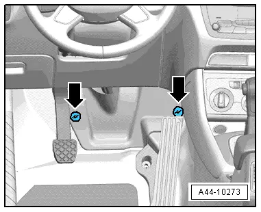
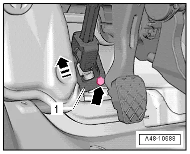
- Remove the footwell trim panel by removing the nuts -arrows-.
- Remove the bolt -arrow- from the universal joint -1-. Then remove the universal joint from the steering gear in direction of -arrow-.
- Remove the front wheels. Refer to → Chapter "Wheels and Tires".
- Secure the subframe. Refer to → Chapter "Subframe, Securing".
Vehicles with 4-cylinder Engine
- Disconnect the connector for the Oil Level Thermal Sensor -G266--arrow- and free up the wire.
Continuation for all vehicles
- If installed, disconnect the connector -2- from the Left Front Level Control System Sensor -G78- or Right Front Level Control Sensor -G289-.
- Remove the nut -4- and free up the coupling rod from the Left Front Level Control System Sensor -G78- or Right Front Level Control Sensor -G289-.

- Remove the bolts -arrows-.

- Remove the left and right nut -1- from the coupling rod -3-.
- Remove the coupling rod -3- from the stabilizer bar -2- on the left and right sides.
- Remove the nuts -arrows-.
 Note
Note
Pay attention during the assembly work that the ball joint rubber boot is not damaged. If necessary protect the ball joint rubber boot against damage.

- Loosen nuts of the track rod ball joint, but do not unscrew yet.
 Note
Note
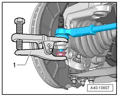
To protect thread, screw nut on pin a few turns.
- Press off tie rod end from wheel bearing housing with Puller - Ball Joint -3287A--1- and then remove nut.
- Remove the bolts -arrows- and then remove the pendulum support from the transmission.

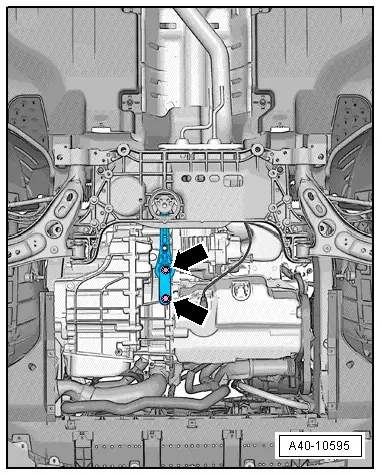
- Remove the bolts -1 and 2- and slightly lower the subframe with the Engine and Gearbox Jack -VAS6931-.
 Caution
There is a risk of damaging the subframe threaded connection threads on the body.
- The subframe bolts on the body must not be loosened or tightened with an impact wrench.
- Always install all bolts by hand for the first few turns.
 Note
Note
Be careful not to overstretch the wire for the steering and the Oil Level Thermal Sensor -G266-.

- Free up the wiring guide from the subframe, to do this remove the expanding clip -arrow-.
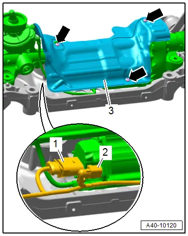
- Remove the bolts -arrows- and remove the heat shield -3-.
- Disconnect the connectors -1 and 2- from the steering gear.
- Unclip the cable holder from the steering gear.
- Unclip all other line mounting clips on steering gear.
- Slowly lower the Engine and Gearbox Jack -VAS6931-.
- Secure the subframe to the Engine and Gearbox Jack -VAS6931- with the accompanying strap.
Installing
Install in reverse order of removal while noting the following:
 Note
Note
- Coat the seal on the steering gear with lubricant such as soft soap before installing.
- After placing steering gear onto universal joint, make sure that seal on steering gear makes contact on assembly plate without kinks and opening to footwell is correctly sealed. Ingress of water and/or noises may be the result.
- Make sure that the sealing surface is clean.
- Install the front wheels. Refer to → Chapter "Wheels and Tires".
- An axle alignment may be required. Refer to → Chapter "Evaluating Need for Axle Alignment".
- On vehicles with electronically controlled damping, perform the function "Adapt the control position" with the Vehicle Diagnostic Tester.
- If the control position was reprogrammed and if the vehicle has lane assist, then it will then be necessary to calibrate the driver assistance systems front camera. Refer to → Chapter "Driver Assistance Systems Front Camera, Calibrating".
- On vehicles with level control system sensor, perform headlamp basic setting. Refer to → Electrical Equipment; Rep. Gr.94; Headlamp, Adjusting.
Tightening Specifications
- Exhaust system bracket.
READ NEXT:
 Subframe, Servicing
Special tools and workshop equipment
required
Bearing Installer - Wheel Hub/Bearing Kit -T10205-
Torque Wrench 1332 40-200Nm -VAG1332-
Hydraulic Press -VAS6178-
Pneumatic/Hydraulic Foot Pu
Stabilizer Bar, Removing and Installing
Special tools and workshop equipment
required
Locating Pins -T10096-
Torque Wrench 1332 40-200Nm -VAG1332-
Engine and Gearbox Jack -VAS6931-
Puller - Ball Joint -3287A-
Removing
-
Subframe, Securing
Special tools and workshop equipment
required
Locating Pins -T10096-
Torque Wrench 1332 40-200Nm -VAG1332-
Engine and Gearbox Jack -VAS6931-
Procedure
- Remove the noise insulation
SEE MORE:
Traffic light information
Description
Applies to: vehicles with traffic light information
Fig. 93 Instrument cluster: traffic light information display
The traffic light information gives you a speed
recommendation in order to reach the next traffic
light when it is green 1, or it informs you of
the wait time at the next re
Driver Assistance Systems Front Camera
Driver Assistance Systems Front Camera, Calibrating
Special tools and workshop equipment
required
Setting Device Basic Set -VAS6430/1-
Wheel Alignment Computer
Vehicle Diagnostic Tester
Calibration is necessary if:
Note
Before calibrating the Driver Assistance Systems Front
