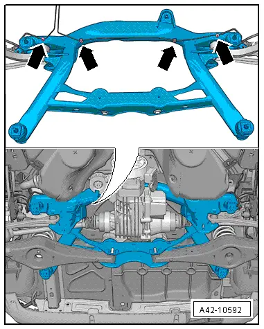
Audi Q3: Subframe, Removing and Installing
Subframe, Removing and installing, FWD Vehicles
Special tools and workshop equipment required
- Locating Pins -T10096-
- Torque Wrench 1332 40-200Nm -VAG1332-
- Engine and Gearbox Jack -VAS6931-
Removing the Subframe and Attachments
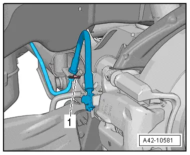
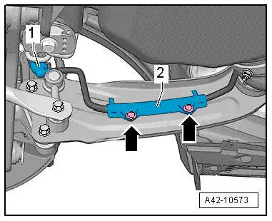
- Disconnect the right and left electromechanical parking brake connector -1- from the brake caliper.
- Remove the bracket -2- by pressing out the rivet inner pins -arrows-.
- Remove the left and right brake caliper and with the brake lines attached, secure to the body. Refer to → Brake System; Rep. Gr.46; Rear Brakes; Brake Caliper, Removing and Installing.

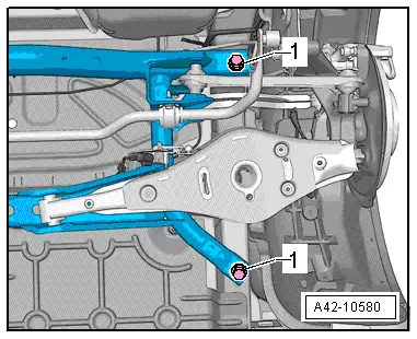
- Disconnect the electrical wires from the ABS speed sensor -1- and free them up.
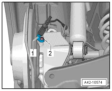
- If the vehicle has electronic damping, disconnect the connector -1- and free it up.

- Disconnect the connector -2- for the Left Rear Level Control System Sensor -G76--1-.
- Free up the wire on the subframe.
- Remove the coil springs. Refer to → Chapter "Spring, Removing and Installing".
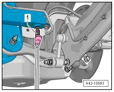
- Remove the bolt -1- and remove it with the washer -2-.
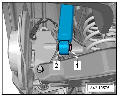
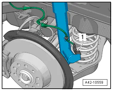
- Remove the clamps -1- on both sides of the vehicle.
- Free up the brake lines from the bracket.
 Note
Note
Do not disconnect the brake line.
- Remove the rear muffler. Refer to → Rep. Gr.26; Exhaust Pipes/Mufflers; Overview - Muffler.
- Remove the underbody trim panels. Refer to → Body Exterior; Rep. Gr.66; Underbody Panel; Underbody Trim Panels, Removing and Installing.
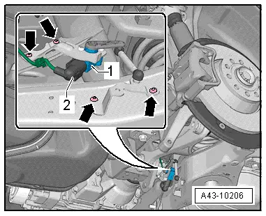
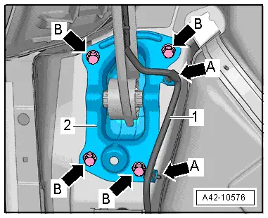
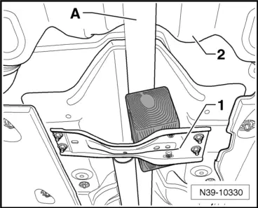
- Remove the wire -1- on the bracket -A arrows-.
- Mark the installation position of the bracket -2- on the body.
- Remove the bolts -B arrows-.
 WARNING
Before -LOOSENING- subframe bolts, secure the vehicle from tipping over (for example load luggage compartment with approximately 50 kg).

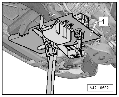
- Move the Engine and Gearbox Jack -VAS6931--1- under the subframe and secure it using the tensioning strap.

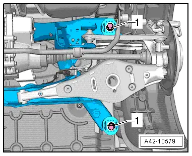
- Remove a front or rear hex bolt -1- on both sides.
 Caution
There is a risk of damaging the subframe threaded connection threads on the body.
- The subframe bolts on the body must not be loosened or tightened with an impact wrench.
- Always install all bolts by hand for the first few turns.
 Note
Note
Only the left side of the vehicle is shown in the illustration.
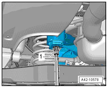
- To secure the subframe, the Locating Pins -T10096- must be installed at the positions -1- one after the other on both sides of the vehicle.
- Secure the subframe position using the locating pins -1-.
 Note
Note
The locating pins may only be tightened to a maximum of 20 Nm, since otherwise the locating pin threads will be damaged.
- Replace the bolts on both sides of the subframe one after the other with the locating pins and tighten to 20 Nm.
The subframe position is now secured.
- Carefully lower the subframe with its components 30 mm maximum.
- Remove the brake line from the clips -arrows-.
 Note
Note
- The clips will get damaged while doing this and will have to be replaced.
- For illustrative purposes, the illustration shows the subframe removed and from the top.
- Lower subframe with attachments.
 Note
Note
When lowering, ensure the brake lines and electrical lines have sufficient clearance.
Install Subframe with Attachments
Install in reverse order of removal. Note the following:
- Install the brake calipers. Refer to → Brake System; Rep. Gr.46; Rear Brakes; Brake Caliper, Removing and Installing.
- An axle alignment may be required. Refer to → Chapter "Evaluating Need for Axle Alignment".
- On vehicles with electronically controlled damping, perform the function "Adapt the control position" with the Vehicle Diagnosis Tester.
- If the control position was reprogrammed and if the vehicle has lane assist, then it will then be necessary to calibrate the driver assistance systems front camera. Refer to → Chapter "Driver Assistance Systems Front Camera, Calibrating".
- On vehicles with level control system sensor, perform headlamp basic setting. Refer to → Electrical Equipment; Rep. Gr.94; Headlamp, Adjusting.

Subframe, Removing and Installing, AWD Vehicles
Special tools and workshop equipment required
- Locating Pins -T10096-
- Torque Wrench 1332 40-200Nm -VAG1332-
- Engine and Gearbox Jack -VAS6931-
Removing the Subframe and Attachments
 Note
Note
The vehicle must be resting on it wheels during any subsequent work where the driveshaft collar bolt must be loosened. Remove the driveshaft twelve point bolt. Refer to → Chapter "Drive Axle Threaded Connection, Loosening and Tightening".
- Disconnect the electrical wires from the ABS speed sensor -1- and free them up.

- If the vehicle has electronic damping, disconnect the connector -1- and free it up.
- Remove the coil springs. Refer to → Chapter "Spring, Removing and Installing".
- Remove the exhaust system muffler. Refer to → Rep. Gr.26; Exhaust Pipes/Mufflers; Overview - Muffler.
- Disconnect the electrical wires to the Haldex clutch, ABS speed sensor and level control system sensor from the connectors, unclip and free them up.
- Remove the bolt -1- and the washer -2-.

- Remove the clip -1- and remove the brake line from the bracket.
 Note
Note
Do not disconnect the brake line.
- Remove the underbody trim panels. Refer to → Body Exterior; Rep. Gr.66; Underbody Panel; Underbody Trim Panels, Removing and Installing.

- Disconnect the right and left electromechanical parking brake connector -1- from the brake caliper.
- Remove the bracket -2- by pressing out the rivet inner pins -arrows-.
- Remove the left and right brake caliper and with the brake lines attached, secure to the body. Refer to → Brake System; Rep. Gr.46; Rear Brakes; Brake Caliper, Removing and Installing.
- Remove the line -1- at mounting bracket -A arrows-.
- Mark installation position of mounting bracket -2- on body.
- Remove the bolts -B arrows-.
- Check for a factory-applied marking (colored dot) on the joint washer and Haldex clutch flange -arrows-. If there is not one, mark the location of the joint washer and the Haldex clutch flange to each other -arrows-.
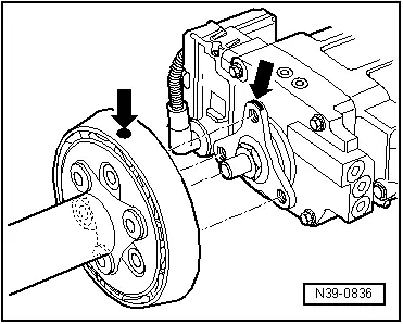
- Remove rear driveshaft tube from rear final drive with joint washer and vibration damper -arrows-.
Audi Q3
- Support the driveshaft -A- on the tunnel brace -1- with a wood block.
- Move rear driveshaft tube as far as possible in direction of transmission.
Audi RS Q3
- Tie up the driveshaft to the body.
Continuation for All Vehicles
- Disconnect the connector -2- and free it up.

 Note
Note
Ignore the -arrows-.
- Disconnect connector to Haldex clutch above final drive.
 WARNING
Before -loosening- subframe bolts, secure vehicle from tipping over, for example, load the luggage compartment with approximately 50 kg.
- Move the Engine and Gearbox Jack -VAS6931--1- under the subframe and secure it using the tensioning strap.
To secure the subframe, the Locating Pins -T10096- must be installed at the positions -1- one after the other on both sides of the vehicle.
 Caution
There is a risk of damaging the subframe threaded connection threads on the body.
- The subframe bolts on the body must not be loosened or tightened with an impact wrench.
- Always install all bolts by hand for the first few turns.
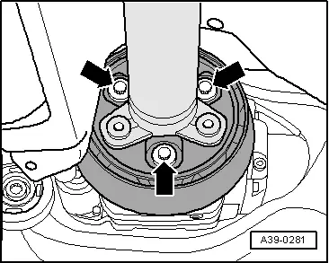
- Remove a hex bolt -1- from both sides.
 Note
Note
Only the left side of the vehicle is shown in the illustration.
- Secure the subframe position with the locating pins -1-.
 Note
Note
The locating pins may only be tightened to a maximum of 20 Nm, since otherwise the locating pin threads will be damaged.
- Replace the bolts on both sides of the subframe one after the other with the locating pins and tighten to 20 Nm.
The subframe position is now secured.
- Carefully lower the subframe with its attachments approximately 2 cm.
 Note
Note
When lowering, make sure there is enough clearance between the brake lines, electrical lines and centering pins to the driveshaft.
- Remove the brake line on both sides from the clips -arrows-.
 Note
Note
The clips will get damaged while doing this and will have to be replaced.
- Carefully lower subframe with components.
 Note
Note
Make sure there is enough clearance for brake lines, electrical lines and driveshaft centering pin when lowering.
Install Subframe with Attachments
Install in reverse order of removal. Note the following:
 Note
Note
Replace the damaged clips on the subframe for the brake line.
- Install the brake calipers. Refer to → Brake System; Rep. Gr.46; Rear Brakes; Brake Caliper, Removing and Installing.
- Connect the propshaft to the rear final drive. Refer to → Rep. Gr.39; Drive Shaft, Drive Shaft, Removing and Installing.
- An axle alignment may be required. Refer to → Chapter "Evaluating Need for Axle Alignment".
- On vehicles with electronically controlled damping, perform the function "Adapt the control position" with the Vehicle Diagnosis Tester.
- If the control position was reprogrammed and if the vehicle has lane assist, then it will then be necessary to calibrate the driver assistance systems front camera. Refer to → Chapter "Driver Assistance Systems Front Camera, Calibrating".
- On vehicles with level control system sensor, perform headlamp basic setting. Refer to → Electrical Equipment; Rep. Gr.94; Headlamp, Adjusting.