Audi Q3: Tie Rod, Removing and Installing
Tie Rod, Removing and Installing, FWD Vehicles
Special tools and workshop equipment required
- Torque Wrench 1331 5-50Nm -VAG1331-
- Torque Wrench 1332 40-200Nm -VAG1332-
Removing
- Measure dimension from center of wheel to lower edge of wheel housing. Refer to → Chapter "Wheel Bearing in Curb Weight, Lifting Vehicles with Coil Spring".
- Remove the affected rear wheel. Refer to → Chapter "Wheels and Tires".
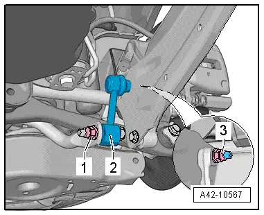
- Remove the nut -1- and pull the coupling rod -2- out of the stabilizer bar.

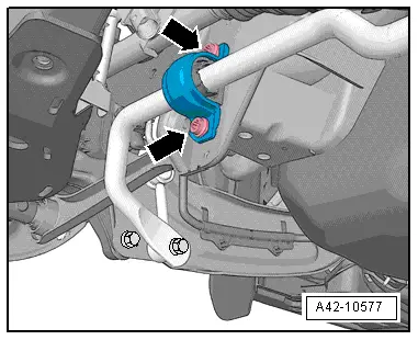
- Remove the bolts -arrows- for the stabilizer bar clamp. Refer to → Chapter "Stabilizer Bar, Removing and Installing".
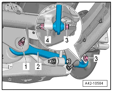
- Remove the nut -4- and bolt -3-.
- Remove the nut -1- and then remove the bolt to the rear.
- Remove the tie rod -2-.

Installing
Installation is reverse of removal, noting the following:
- The tie rod may only be fastened when the dimension between wheel hub center and lower edge of wheel housing, measured before assembly, is achieved. Refer to → Chapter "Wheel Bearing in Curb Weight, Lifting Vehicles with Coil Spring".
- An axle alignment may be required. Refer to → Chapter "Evaluating Need for Axle Alignment".
Tie Rod, Removing and Installing, AWD Vehicles
Special tools and workshop equipment required
- Torque Wrench 1331 5-50Nm -VAG1331-
- Torque Wrench 1332 40-200Nm -VAG1332-
Removing
- Measure dimension from center of wheel to lower edge of wheel housing. Refer to → Chapter "Wheel Bearing in Curb Weight, Lifting Vehicles with Coil Spring".
- Remove the affected rear wheel. Refer to → Chapter "Wheels and Tires".
- Remove the nut -1- and pull the coupling rod -2- out of the stabilizer bar.
- Remove the bolts -arrows- for the stabilizer bar clamp.

- Remove the nut -4- and bolt -3-.
- Remove the nut -1- and then remove the bolt to the rear.
- Remove the bolt -2-.
Installing
Installation is reverse of removal, noting the following:
- The control arm may only be fastened if the dimension between the wheel hub center and lower edge of wheel housing, measured before assembly, is achieved. Refer to → Chapter "Wheel Bearing in Curb Weight, Lifting Vehicles with Coil Spring".
- Install the coil spring. Refer to → Chapter "Spring, Removing and Installing".
- An axle alignment may be required. Refer to → Chapter "Evaluating Need for Axle Alignment".
READ NEXT:
 Suspension Strut/Shock Absorber, Spring
Overview - Suspension Strut, Shock Absorber and Spring
1 - Lower Spring Support
Spring end rotated up to stop
2 - Coil Spring
Removing and installing. Refer to
→&
Overview - Wheel Bearing
Overview - Wheel Bearing, Vehicles with FWD
1 - Cover
2 - Bracket
3 - Bolt
50 Nm + 45º
Always replace if removed
4 - Coupling Rod
5 -
Wheel Bearing Housing, Removing and Installing
Wheel Bearing Housing, Removing and Installing, FWD Vehicles
Special tools and workshop equipment
required
Torque Wrench 1332 40-200Nm -VAG1332-
Removing
- Measure dimension from cente
SEE MORE:
LED Headlamp, Adjusting
Checking and adjusting conditions
Tire pressure is OK.
The headlamp glass must be clean and dry.
The headlamp glass must not be damaged.
Headlamp reflectors and bulbs are OK.
The vehicle must be under load.
Vehicle load on driver seat in otherwise unloaded vehicle
(curb weight).
Overview - Release Cable
Overview - Latch Release Cable
1 - Right Hood Latch
Removing and installing. Refer to
→ Chapter "Hood Latch, Removing and Installing".
2 - Hood Latch Cable
Removing and installing. Refer to
→ Chapter "Release Cable, Removing and Installing".
3&n
